
Circuit Documentation
Summary
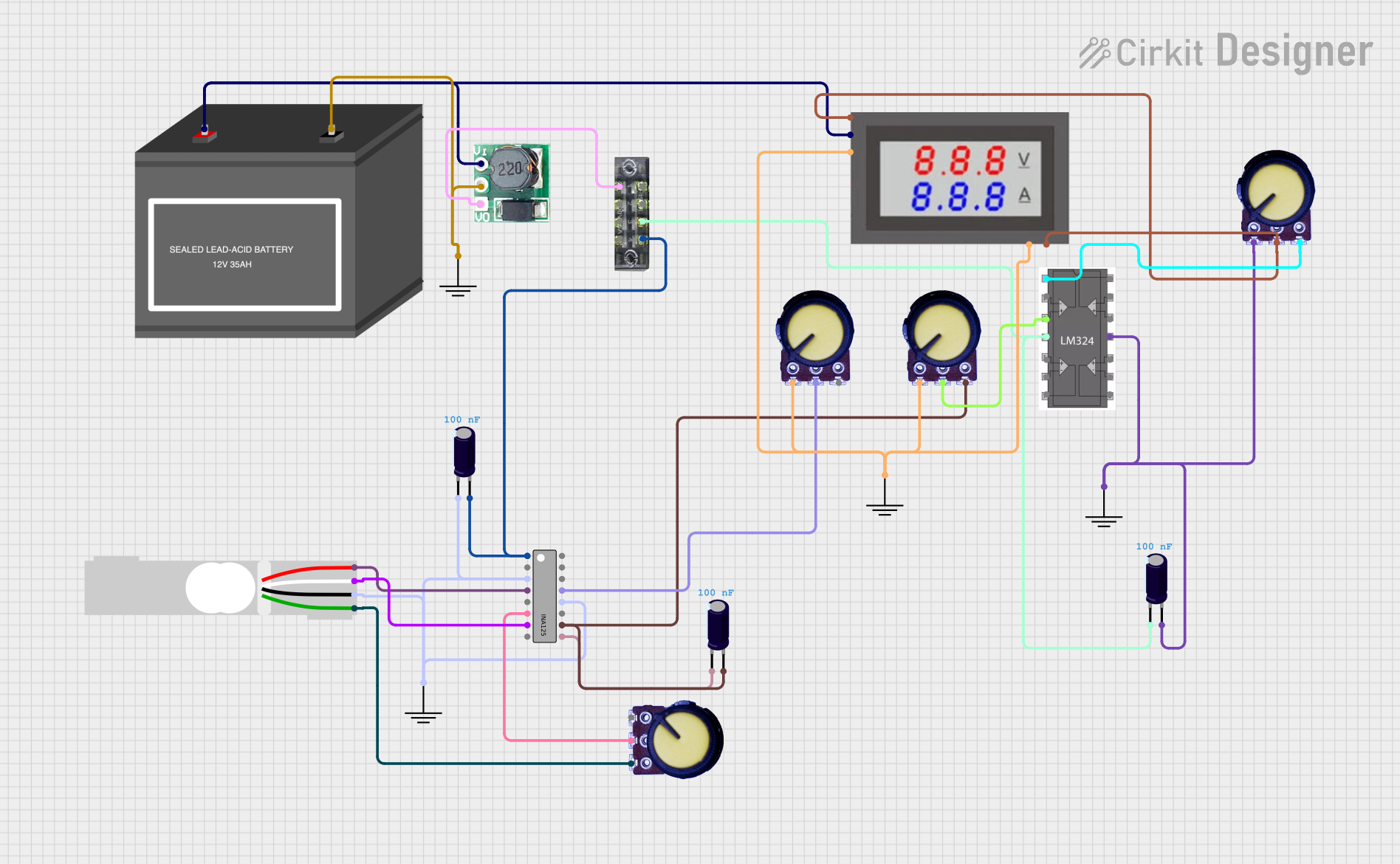
This document provides a detailed overview of a circuit design that includes various components such as an instrumentation amplifier (INA125), operational amplifier (LM324), load cell, potentiometers, capacitors, a step-up boost converter, a mini digital volt/ammeter, and a 12V battery. The circuit is designed to amplify signals from a load cell, provide voltage regulation, and measure voltage and current.
Component List
INA125
- Description: Instrumentation Amplifier
- Pins: V+, SLEEP, V-, V_ref Out, IA_ref, V_in +, V_in -, R_G, V_REF 10, V_REF 5, V_REF 2.5, V_REF BG, V_REF OUT, Sense, V_O
LM324
- Description: Quad Operational Amplifier
- Pins: out1, + in 1, VCC, + in 2, - in 2, out 2, out 3, - in 3, + in 3, GND, + in 4, - in 4, out 4, - in 1
12V Battery (mini)
- Description: Power Source
- Pins: -, +
Step Up Boost 3v-5v
- Description: Voltage Boost Converter
- Pins: Vi, GND, Vo
Electrolytic Capacitor
- Description: Capacitor
- Pins: -, +
- Properties: Capacitance = 1e-7 Farads
Potentiometer
- Description: Variable Resistor
- Pins: GND, Output, VCC
Load Cell - Red/white/black/green
- Description: Load Cell
- Pins: E+, A-, E-, A+
Mini Digital Volt/Ammeter
- Description: Voltage and Current Meter
- Pins: Gnd, Vin, Vread, Vsupply
GND
- Description: Ground
- Pins: GND
Terminal Block
- Description: Terminal Block
- Pins: 1, 2, 3, 4, 5, 6, 7, 8
Wiring Details
INA125
- V+: Connected to Terminal Block pin 7 and Electrolytic Capacitor (+)
- V-: Connected to GND, Electrolytic Capacitor (-), Load Cell (E-), and V_REF OUT
- V_ref Out: Connected to Load Cell (E+)
- V_in +: Connected to Potentiometer (Output)
- V_in -: Connected to Load Cell (A-)
- V_REF BG: Connected to Potentiometer (Output)
- V_O: Connected to Potentiometer (VCC) and Electrolytic Capacitor (+)
- R_G: Connected to Electrolytic Capacitor (-)
LM324
- out1: Connected to Potentiometer (VCC)
- + in 1: Connected to Potentiometer (Output)
- VCC: Connected to Terminal Block pin 5 and Electrolytic Capacitor (-)
- GND: Connected to GND, Electrolytic Capacitor (+), and Potentiometer (GND)
12V Battery (mini)
- -: Connected to Step Up Boost (GND)
- +: Connected to Step Up Boost (Vi) and Mini Digital Volt/Ammeter (Vsupply)
Step Up Boost 3v-5v
- GND: Connected to GND and 12V Battery (-)
- Vi: Connected to 12V Battery (+) and Mini Digital Volt/Ammeter (Vsupply)
- Vo: Connected to Terminal Block pin 2
Electrolytic Capacitor
- Instance 1:
- +: Connected to Terminal Block pin 7 and INA125 (V+)
- -: Connected to GND, Load Cell (E-), INA125 (V-), and V_REF OUT
- Instance 2:
- +: Connected to Potentiometer (VCC) and INA125 (V_O)
- -: Connected to INA125 (R_G)
- Instance 3:
- +: Connected to LM324 (GND) and Potentiometer (GND)
- -: Connected to Terminal Block pin 5 and LM324 (VCC)
Potentiometer
- Instance 1:
- Output: Connected to INA125 (V_in +)
- Instance 2:
- Output: Connected to INA125 (V_REF BG)
- Instance 3:
- VCC: Connected to LM324 (out1)
- Output: Connected to LM324 (+ in 1)
- Instance 4:
- VCC: Connected to Electrolytic Capacitor (+) and INA125 (V_O)
- Output: Connected to Mini Digital Volt/Ammeter (Vin) and Vread
- GND: Connected to Mini Digital Volt/Ammeter (Gnd) and GND
Load Cell
- E+: Connected to INA125 (V_ref Out)
- A-: Connected to INA125 (V_in -)
- E-: Connected to GND, Electrolytic Capacitor (-), and INA125 (V-)
- A+: Connected to Potentiometer (VCC)
Mini Digital Volt/Ammeter
- Gnd: Connected to GND and Potentiometer (GND)
- Vin: Connected to Potentiometer (Output)
- Vread: Connected to Potentiometer (Output)
- Vsupply: Connected to Step Up Boost (Vi) and 12V Battery (+)
GND
- Instance 1: Connected to Electrolytic Capacitor (-), Load Cell (E-), and INA125 (V-)
- Instance 2: Connected to Step Up Boost (GND) and 12V Battery (-)
- Instance 3: Connected to LM324 (GND), Electrolytic Capacitor (+), and Potentiometer (GND)
- Instance 4: Connected to Mini Digital Volt/Ammeter (Gnd) and Potentiometer (GND)
Terminal Block
- Pin 2: Connected to Step Up Boost (Vo)
- Pin 5: Connected to LM324 (VCC) and Electrolytic Capacitor (-)
- Pin 7: Connected to Electrolytic Capacitor (+) and INA125 (V+)
Code
There is no embedded code provided for this circuit.
This document provides a comprehensive overview of the circuit, including a detailed component list and wiring details for each component. The circuit is designed to amplify signals from a load cell, provide voltage regulation, and measure voltage and current.