Cirkit Designer
Your all-in-one circuit design IDE
Home /
Project Documentation
Arduino UNO-Based Biometric and Voice-Controlled Security System
Circuit Documentation
Summary
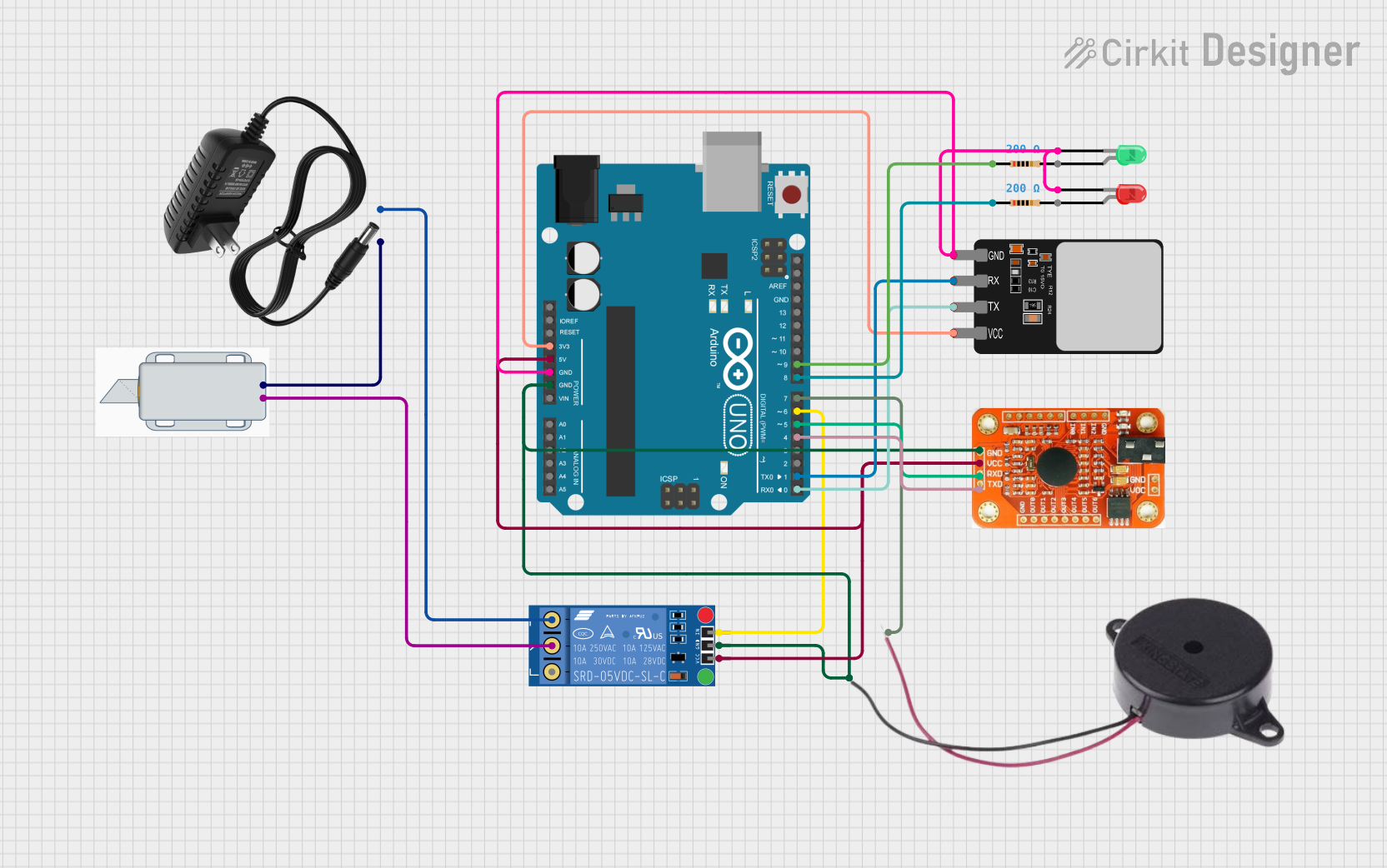
The circuit in question is designed to control access through a 12V Solenoid Lock, which is managed by an Arduino UNO microcontroller. The system uses a Fingerprint Scanner and a Voice Recognition Module as authentication methods. Upon successful authentication, the lock can be opened for a predetermined duration. The circuit also includes visual indicators (LEDs) and an audible indicator (Buzzer) to provide status feedback.
Component List
Arduino UNO
- Microcontroller board based on the ATmega328P.
- It has 14 digital input/output pins, 6 analog inputs, a 16 MHz quartz crystal, a USB connection, a power jack, an ICSP header, and a reset button.
Fingerprint Scanner
- A biometric sensor that captures fingerprints for authentication purposes.
- It typically operates at 3.3V and communicates via serial TX/RX lines.
Voice Recognition Module
- A module capable of recognizing pre-programmed voice commands.
- It requires a power supply and communicates with the microcontroller through serial lines.
KF-301 Relay
- An electromechanical switch used to control the high-power circuit of the solenoid lock.
- It has a signal input, power supply, and ground connections, along with Normally Closed (NC), Common (C), and Normally Open (NO) contacts.
12V Solenoid Lock
- An electrically-controlled lock that operates at 12V.
- It has two terminals for power supply connections.
Buzzer
- An audio signaling device that emits a tone when powered.
- It has positive and negative terminals.
LED: Two Pin (red)
- A red light-emitting diode that indicates power or status.
- It has an anode and cathode for connection to the power supply and ground, respectively.
LED: Two Pin (green)
- A green light-emitting diode used for status indication.
- Similar to the red LED, it has an anode and cathode.
12V Power Supply
- Provides the necessary power for the 12V components in the circuit, such as the solenoid lock.
Resistor (200 Ohms)
- A passive two-terminal electrical component that implements electrical resistance as a circuit element.
- Used for current limiting or voltage dropping.
Wiring Details
Arduino UNO
3.3Vto Fingerprint ScannerVCC5Vto Voice Recognition ModuleVCCand KF-301 RelaypowerGNDto Red LEDcathode, Fingerprint ScannerGND, Green LEDcathode, Voice Recognition ModuleGND, BuzzerNEGATIVE, and KF-301 RelaygroundD9to Resistor (connected to Red LEDanode)D8to Resistor (connected to Green LEDanode)D7to BuzzerPOSITIVED6to KF-301 RelaysignalD5to Voice Recognition ModuleRDXD4to Voice Recognition ModuleRTXD1to Fingerprint ScannerRXD0to Fingerprint ScannerTX
Fingerprint Scanner
VCCto Arduino UNO3.3VTXto Arduino UNOD0RXto Arduino UNOD1GNDto Arduino UNOGND
Voice Recognition Module
VCCto Arduino UNO5VRDXto Arduino UNOD5RTXto Arduino UNOD4GNDto Arduino UNOGND
KF-301 Relay
signalto Arduino UNOD6powerto Arduino UNO5Vgroundto Arduino UNOGNDCto 12V Solenoid Lock-NOto 12V Power Supply-
12V Solenoid Lock
+to 12V Power Supply+-to KF-301 RelayC
Buzzer
POSITIVEto Arduino UNOD7NEGATIVEto Arduino UNOGND
LED: Two Pin (red)
anodethrough a 200 Ohm Resistor to Arduino UNOD9cathodeto Arduino UNOGND
LED: Two Pin (green)
anodethrough a 200 Ohm Resistor to Arduino UNOD8cathodeto Arduino UNOGND
12V Power Supply
+to 12V Solenoid Lock+-to KF-301 RelayNO
Resistor (200 Ohms)
- One resistor connected between Arduino UNO
D9and Red LEDanode - Another resistor connected between Arduino UNO
D8and Green LEDanode
Documented Code
#include <Adafruit_Fingerprint.h>
#include <VoiceRecognitionV3.h>

// Define pins
#define VOICE_RX_PIN 4
#define VOICE_TX_PIN 5
#define RELAY_PIN 6      // Define relay control pin
#define BUZZER_PIN 7     // Define buzzer pin
#define RED_LED_PIN 8    // Define red LED pin
#define GREEN_LED_PIN 9  // Define green LED pin

// Hardware serial for fingerprint sensor (pins 0 and 1)
#define fingerprintSerial Serial

// Create instances
Adafruit_Fingerprint finger = Adafruit_Fingerprint(&fingerprintSerial);
VR myVR(VOICE_RX_PIN, VOICE_TX_PIN);  // Voice recognition instance

// Variables
bool fingerprintAuthenticated = false;
bool voiceAuthenticated = false;
bool accessGranted = false;
unsigned long unlockStartTime = 0;
const unsigned long unlockDuration = 10000; // 10 seconds unlock duration
const unsigned long lockoutDuration = 120000; // 120 seconds lockout duration
unsigned long lockoutStartTime = 0;
bool inLockout = false;

void setup() {
  // Initialize serial communication
  Serial.begin(9600);
  delay(100);

  // Initialize relay
  pinMode(RELAY_PIN, OUTPUT);
  digitalWrite(RELAY_PIN, HIGH);  // Ensure relay is off initially (active low)

  // Initialize buzzer
  pinMode(BUZZER_PIN, OUTPUT);
  digitalWrite(BUZZER_PIN, LOW);  // Buzzer off initially

  // Initialize LEDs
  pinMode(RED_LED_PIN, OUTPUT);
  pinMode(GREEN_LED_PIN, OUTPUT);
  digitalWrite(RED_LED_PIN, HIGH); // Red LED on as power indicator
  digitalWrite(GREEN_LED_PIN, LOW); // Green LED off initially

  // Initialize fingerprint sensor using hardware serial
  fingerprintSerial.begin(57600);
  finger.begin(57600);
  if (finger.verifyPassword()) {
    Serial.println("Found fingerprint sensor!");
  } else {
    Serial.println("Did not find fingerprint sensor :(");
    while (1) {
      delay(1);
    }
  }

  finger.getTemplateCount();
  Serial.print("Sensor contains ");
  Serial.print(finger.templateCount);
  Serial.println(" templates");

  // Initialize voice recognition module
  myVR.begin(9600); // Initialize SoftwareSerial for VR module

  // Load voice commands: 0-5
  for (uint8_t i = 0; i <= 5; i++) {
    if (myVR.load(i) >= 0) {  // Load each command
      Serial.print("Command '");
      Serial.print(i);
      Serial.println("' loaded.");
    } else {
      Serial.print("Failed to load command '");
      Serial.print(i);
      Serial.println("'.");
    }
  }

  Serial.println("Waiting for valid finger...");
}

void loop() {
  // Handle lockout state
  if (inLockout) {
    if (millis() - lockoutStartTime >= lockoutDuration) {
      inLockout = false;
      Serial.println("Lockout period ended.");
    } else {
      return; // Stay in lockout
    }
  }

  // Check fingerprint authentication
  if (!fingerprintAuthenticated && !inLockout) {
    int fingerID = getFingerprintIDez();
    if (fingerID >= 0 && fingerID <= 6) {
      fingerprintAuthenticated = true;
      digitalWrite(GREEN_LED_PIN, HIGH);  // Green LED on after fingerprint recognition
      Serial.println("Fingerprint authenticated. Please provide voice command.");
      delay(2000); // Hold green LED on for 2 seconds
      digitalWrite(GREEN_LED_PIN, LOW);   // Turn off green LED after 2 seconds
      unlockStartTime = millis(); // Record time of fingerprint authentication for voice input timing
    }
  }

  // Check voice authentication if fingerprint is authenticated
  if (fingerprintAuthenticated && !voiceAuthenticated && !inLockout) {
    uint8_t buf[64];
    int ret = myVR.recognize(buf, 50);
    if (ret > 0) {
      if (buf[1] >= 0 && buf[1] <= 5) { // Command IDs 0-5
        voiceAuthenticated = true;