
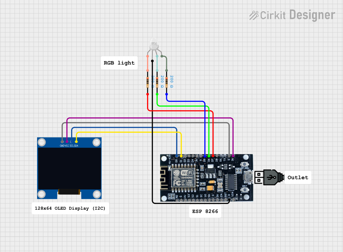
Circuit Documentation
Summary
This document provides a detailed description of a circuit that includes an ESP8266 microcontroller, a 128x64 OLED display, an RGB LED, and several resistors. The circuit is designed to interface the ESP8266 with the OLED display via I2C communication and control the RGB LED through GPIO pins with current-limiting resistors.
Component List
128x64 OLED Display (I2C IIC SPI Serial)
- Pins: GND, SDA, SCL, VCC
- Description: A monochrome OLED display module that supports I2C, IIC, and SPI communication protocols.
ESP8266
- Pins: 3V, G, D8, D7, D6, D5, D4, D3, D2, D1, D0, A0, S3, S2, S1, SC, S0, SK, EN, VIN, RST, VU
- Description: A low-cost Wi-Fi microchip with full TCP/IP stack and microcontroller capability.
RGB LED (Wokwi compatible)
- Pins: R, COM, G, B
- Description: A common-anode RGB LED that can emit red, green, and blue light.
Resistor
- Pins: pin1, pin2
- Description: A 200 Ohm resistor used for current limiting.
- Properties:
- Resistance: 200 Ohms
USB Power
- Pins: +, -
- Description: A USB power source for providing power to the circuit.
Wiring Details
128x64 OLED Display (I2C IIC SPI Serial)
- GND is connected to G of the ESP8266.
- SDA is connected to D1 of the ESP8266.
- SCL is connected to D0 of the ESP8266.
- VCC is connected to 3V of the ESP8266.
ESP8266
- G is connected to GND of the OLED Display.
- D1 is connected to SDA of the OLED Display.
- D0 is connected to SCL of the OLED Display.
- 3V is connected to VCC of the OLED Display.
- D7 is connected to pin2 of a Resistor.
- D6 is connected to pin2 of another Resistor.
- D5 is connected to pin2 of another Resistor.
- G is connected to COM of the RGB LED.
RGB LED (Wokwi compatible)
- COM is connected to G of the ESP8266.
- R is connected to pin1 of a Resistor.
- G is connected to pin1 of another Resistor.
- B is connected to pin1 of another Resistor.
Resistors
- Resistor 1:
- pin1 is connected to R of the RGB LED.
- pin2 is connected to D7 of the ESP8266.
- Resistor 2:
- pin1 is connected to G of the RGB LED.
- pin2 is connected to D6 of the ESP8266.
- Resistor 3:
- pin1 is connected to B of the RGB LED.
- pin2 is connected to D5 of the ESP8266.
Code
There is no code provided for the microcontrollers in this circuit.
This document provides a comprehensive overview of the components and their interconnections in the circuit. For further details or modifications, please refer to the specific datasheets of the components used.