
Arduino Mega 2560-Controlled Servo System with Bluetooth and Sensor Interface
View and Edit Project In Cirkit Designer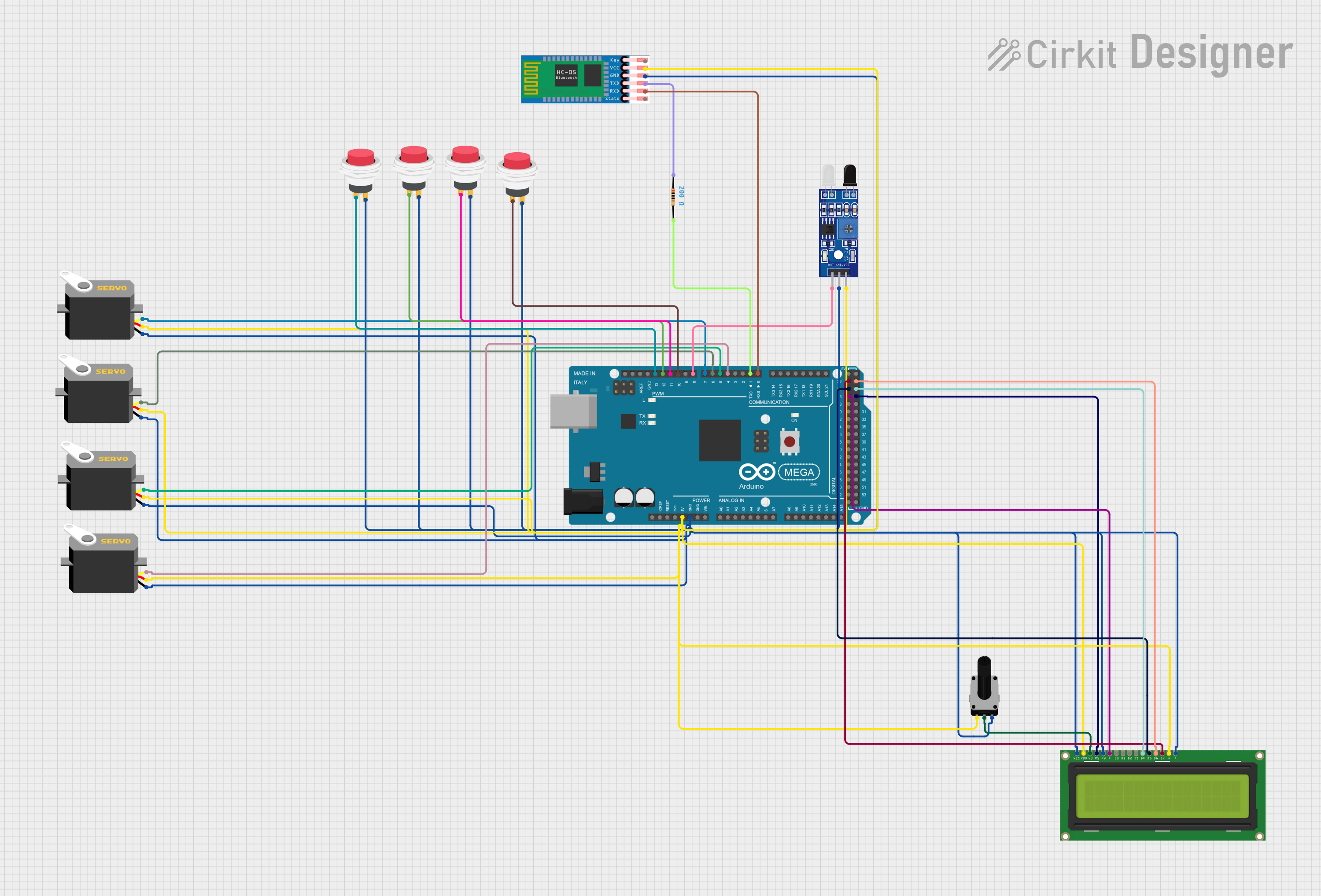
Circuit Documentation
Summary
This document provides a detailed overview of a circuit designed to interface various components with an Arduino Mega 2560 microcontroller. The circuit includes input devices such as rotary potentiometers and push switches, output devices like servos and an LCD display, a Bluetooth module (HC-05), and an IR sensor (FC-51). The circuit is powered by the Arduino's 5V output and includes a common ground net connecting all components. The LCD display is interfaced with the Arduino through digital pins for data and control signals. Servos are controlled via PWM signals from the Arduino. The HC-05 Bluetooth module communicates with the Arduino through serial communication, and the IR sensor is connected to a digital input pin for detection purposes.
Component List
Rotary Potentiometer
- Description: A variable resistor with three terminals: two end terminals and one wiper terminal.
- Properties: 10,000 Ohms resistance.
Push Switches (4x)
- Description: Momentary push-button switches with two terminals: input and output.
Sensor FC-51 IR
- Description: An infrared sensor module with digital output.
HC-05 Bluetooth Module
- Description: A Bluetooth module with serial communication capability.
LCD Display 16x2
- Description: A 16x2 character LCD display with backlight.
Servos (4x)
- Description: Rotary actuators with three terminals: ground, power, and control pulse.
Arduino Mega 2560
- Description: A microcontroller board based on the ATmega2560 with numerous digital and analog I/O pins.
Resistor
- Description: A passive two-terminal electrical component that implements electrical resistance.
- Properties: 200 Ohms resistance.
Wiring Details
Rotary Potentiometer
leg1connected to Arduino Mega 2560's 5V.wiperconnected to LCD Display 16x2'sVO.leg2connected to common ground net.
Push Switches
Input +of each switch connected to individual Arduino Mega 2560's digital pins (D10 PWM, D11 PWM, D12 PWM, D13 PWM).Output +of each switch connected to common ground net.
Sensor FC-51 IR
OUTconnected to Arduino Mega 2560's D8 PWM.GNDconnected to common ground net.VCCconnected to Arduino Mega 2560's 5V.
HC-05 Bluetooth Module
ENnot connected.VCCconnected to Arduino Mega 2560's 5V.GNDconnected to common ground net.TXDconnected to Resistor (200 Ohms) then to common ground net.RXDconnected to Arduino Mega 2560's D0 RX0.STATEnot connected.
LCD Display 16x2
LEDK,RW,VSSconnected to common ground net.LEDA,VDDconnected to Arduino Mega 2560's 5V.DB7connected to Arduino Mega 2560's D22.DB6connected to Arduino Mega 2560's D23.DB5connected to Arduino Mega 2560's D24.DB4connected to Arduino Mega 2560's D25.Econnected to Arduino Mega 2560's D26.RSconnected to Arduino Mega 2560's D27.VOconnected to Rotary Potentiometer'swiper.
Servos
gndof each servo connected to common ground net.vccof each servo connected to Arduino Mega 2560's 5V.pulseof each servo connected to individual Arduino Mega 2560's digital pins (D4 PWM, D5 PWM, D6 PWM, D7 PWM).
Resistor
pin1connected to HC-05'sTXD.pin2connected to common ground net.
Documented Code
Arduino Mega 2560 - sketch.ino
void setup() {
  // put your setup code here, to run once:

}

void loop() {
  // put your main code here, to run repeatedly:

}
Arduino Mega 2560 - documentation.txt
No additional documentation provided for the code.
This concludes the circuit documentation. The circuit is designed for modularity and ease of expansion, with the Arduino Mega 2560 at its core, providing ample I/O for various components and future enhancements.