
Arduino UNO Controlled IR Sensor Array with I2C LCD Display and Servo Integration
View and Edit Project In Cirkit Designer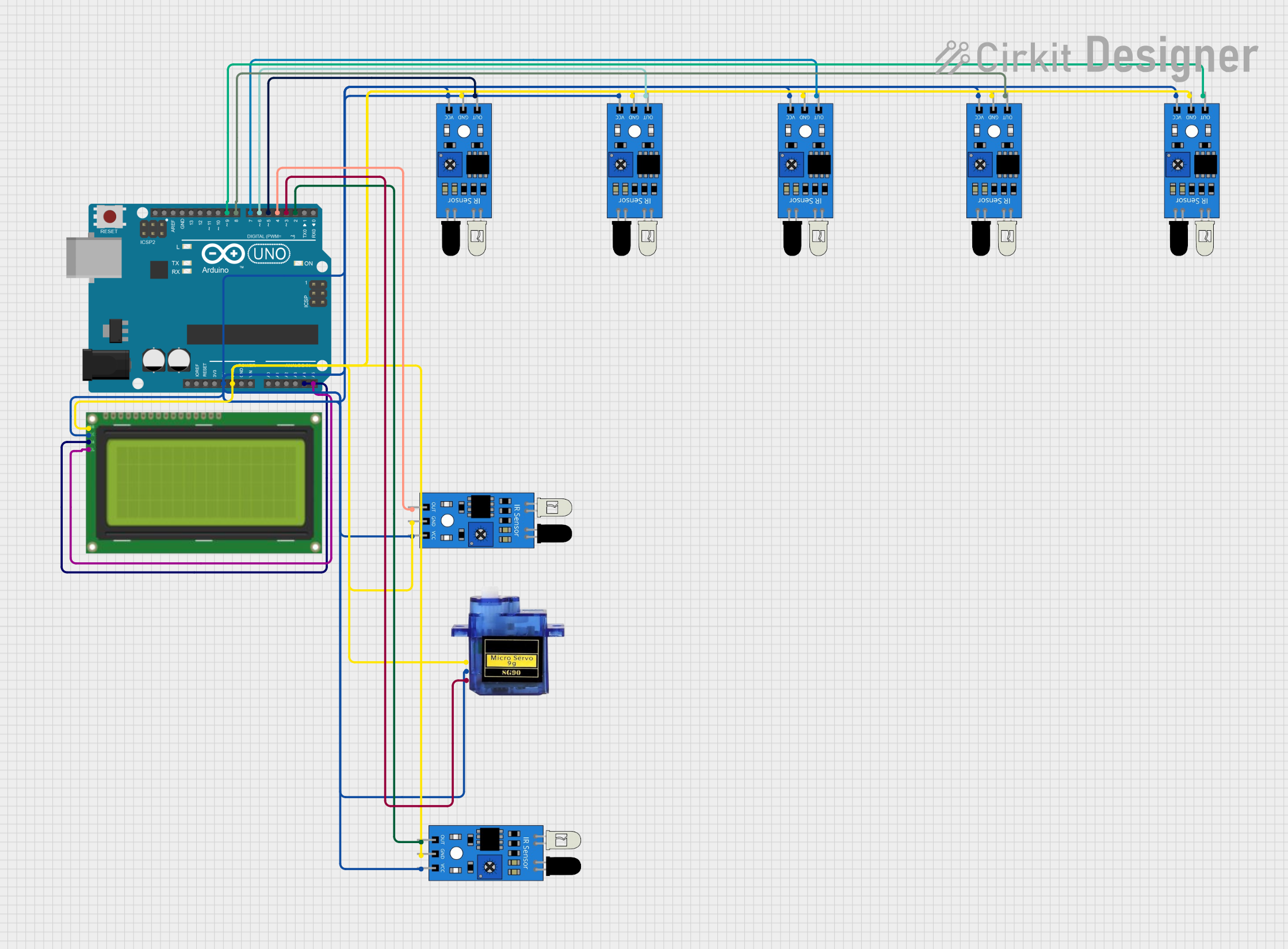
Circuit Documentation
Summary
The circuit in question is designed around an Arduino UNO microcontroller, which serves as the central processing unit. The circuit includes multiple infrared (IR) sensors, an I2C-compatible LCD display (20x4), and a micro servo motor (9G). The IR sensors are likely used for detecting objects or motion, while the LCD display provides a user interface for displaying information. The micro servo is controlled by the Arduino and can be used for precise movement or positioning.
Component List
Arduino UNO
- Microcontroller board based on the ATmega328P
- It has 14 digital input/output pins, 6 analog inputs, a 16 MHz quartz crystal, a USB connection, a power jack, an ICSP header, and a reset button.
Lcd 20x4 i2c
- An alphanumeric liquid crystal display with 20 characters per line and 4 lines.
- It has an I2C interface for communication, which reduces the number of pins needed for operation.
IR Sensor
- An infrared sensor capable of detecting infrared light emitted from objects in its field of view.
- Typically used for proximity or motion detection.
Micro Servo 9G
- A small and lightweight servo motor suitable for applications requiring simple motion tasks.
- Operates on 5V and receives PWM signals for position control.
Wiring Details
Arduino UNO
- 5V and GND pins are used to power the IR sensors, the LCD display, and the micro servo.
- Analog pins A4 (SDA) and A5 (SCL) are used for I2C communication with the LCD display.
- Digital pins D2 to D9 are used to interface with the IR sensors' output pins.
- Digital pin D3 is used to send PWM signals to the micro servo.
Lcd 20x4 i2c
- Powered by 5V and GND from the Arduino UNO.
- SCA and SCL pins are connected to the Arduino's A4 (SDA) and A5 (SCL) pins for I2C communication.
IR Sensors
- Each sensor's VCC and GND are connected to the Arduino's 5V and GND, respectively.
- The output pin of each sensor is connected to a unique digital pin on the Arduino (D2 to D9).
Micro Servo 9G
- Powered by 5V and GND from the Arduino UNO.
- The PWM signal pin is connected to the Arduino's D3 pin.
Documented Code
void setup() {
  // put your setup code here, to run once:

}

void loop() {
  // put your main code here, to run repeatedly:

}
The provided code is a template with empty setup() and loop() functions, which are the standard structure for Arduino sketches. The setup() function is intended to contain initialization code that runs once when the microcontroller is powered on or reset. The loop() function is for code that runs continuously as long as the Arduino is powered.
Additional code is required to initialize the I2C communication for the LCD, to read inputs from the IR sensors, and to control the micro servo based on the sensor inputs. This code is not provided in the input and would need to be written to create a functional circuit application.