
ESP8266 NodeMCU and ESP32-CAM Controlled Robotic Vehicle with IR Sensors and Motor Driver
View and Edit Project In Cirkit Designer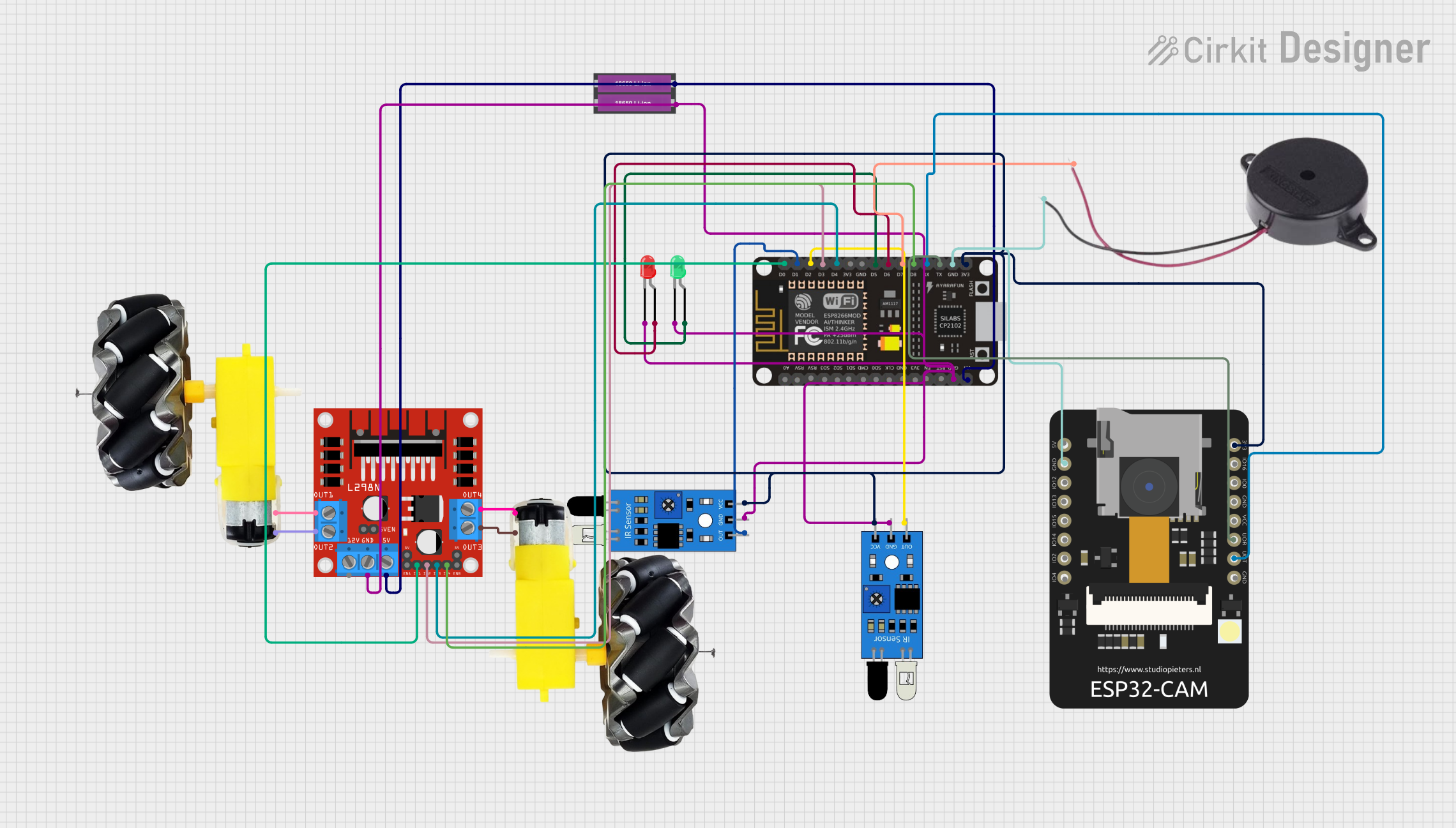
Circuit Documentation
Summary
This circuit integrates various components including microcontrollers, sensors, actuators, and power sources to create a system capable of sensing, processing, and actuating based on the inputs from the IR sensors. The core of the circuit is based on the ESP8266 NodeMCU microcontroller, which interfaces with an ESP32 CAM module, IR sensors, LEDs, a buzzer, a motor driver, and motors with wheels. The circuit is powered by a pair of 18650 Li-ion batteries.
Component List
Microcontrollers
- ESP8266 NodeMCU: A Wi-Fi enabled microcontroller with multiple digital pins, analog input, and serial communication capabilities.
- ESP32 CAM: A camera module with Wi-Fi capabilities that can be used for image processing and IoT applications.
Sensors
- IR Sensor: Used to detect obstacles or measure distances by emitting and receiving infrared light.
Actuators
- LED (Green): A green light-emitting diode used as an indicator or for signaling purposes.
- LED (Red): A red light-emitting diode used as an indicator or for signaling purposes.
- Buzzer: An audible signaling device that can be used for alerts or notifications.
- L298N DC Motor Driver: A module that can control the speed and direction of two DC motors.
- Motor and Wheels: The actuation component that enables movement, driven by the motor driver.
Power Source
- 18650 Li-ion Battery x 2: Provides the necessary power to the circuit components.
Wiring Details
ESP8266 NodeMCU
- D0: Connected to IN1 on the L298N DC motor driver.
- D1: Connected to the 'out' pin of one IR sensor.
- D2: Connected to the 'out' pin of another IR sensor.
- D3: Connected to IN2 on the L298N DC motor driver.
- D4: Connected to IN3 on the L298N DC motor driver.
- D5: Connected to the anode of the green LED.
- D6: Connected to the anode of the red LED.
- D7: Connected to the positive pin of the buzzer.
- D8: Connected to IN4 on the L298N DC motor driver.
- RX: Connected to TX on the ESP32 CAM.
- TX: Connected to RX on the ESP32 CAM.
- 3V3: Connected to the 'vcc' pins of both IR sensors and the 3.3V pin of the ESP32 CAM.
- GND: Common ground with the buzzer, ESP32 CAM, and other components.
- VIN: Connected to the positive terminal of the 18650 Li-ion batteries.
ESP32 CAM
- 5V: Not connected in the provided net list.
- GND: Common ground with other components.
- GPIOs: Not connected in the provided net list.
- 3.3V: Connected to the 3V3 pin of the ESP8266 NodeMCU.
IR Sensor
- out: Connected to D1 and D2 on the ESP8266 NodeMCU for each sensor respectively.
- gnd: Common ground with other components.
- vcc: Connected to the 3V3 pin of the ESP8266 NodeMCU.
LED: Two Pin (Green and Red)
- anode (Green LED): Connected to D5 on the ESP8266 NodeMCU.
- cathode (Green LED): Common ground with other components.
- anode (Red LED): Connected to D6 on the ESP8266 NodeMCU.
- cathode (Red LED): Common ground with other components.
Buzzer
- POSITIVE: Connected to D7 on the ESP8266 NodeMCU.
- NEGATIVE: Common ground with other components.
L298N DC Motor Driver
- IN1, IN2, IN3, IN4: Controlled by D0, D3, D4, and D8 on the ESP8266 NodeMCU respectively.
- OUT1, OUT2, OUT3, OUT4: Connected to the motors and wheels.
- 12V, 5V: Not connected in the provided net list.
- GND: Common ground with other components.
- 5V-ENA-JMP-I, 5V-ENA-JMP-O, +5V-J1, +5V-J2, ENA, ENB: Not connected in the provided net list.
Motor and Wheels
- vcc: Connected to OUT2 and OUT4 on the L298N DC motor driver for each motor respectively.
- GND: Connected to OUT1 and OUT3 on the L298N DC motor driver for each motor respectively.
18650 Li-ion Battery x 2
- +: Connected to the VIN pin of the ESP8266 NodeMCU and the 5V pin of the L298N DC motor driver.
- -: Common ground with other components.
Documented Code
ESP8266 NodeMCU Code (sketch.ino)
void setup() {
  // put your setup code here, to run once:

}

void loop() {
  // put your main code here, to run repeatedly:

}
ESP32 CAM Code
No code provided for the ESP32 CAM.
Motor and Wheels Code (sketch.ino)
void setup() {
  // put your setup code here, to run once:

}

void loop() {
  // put your main code here, to run repeatedly:

}
Note: The provided code for the microcontrollers is a template with empty setup and loop functions. Actual functionality needs to be implemented based on the requirements of the circuit's application.