Cirkit Designer
Your all-in-one circuit design IDE
Home /
Project Documentation
Arduino Nano and ESP-8266 Based Health Monitoring System with GSM Reporting
Circuit Documentation
Summary
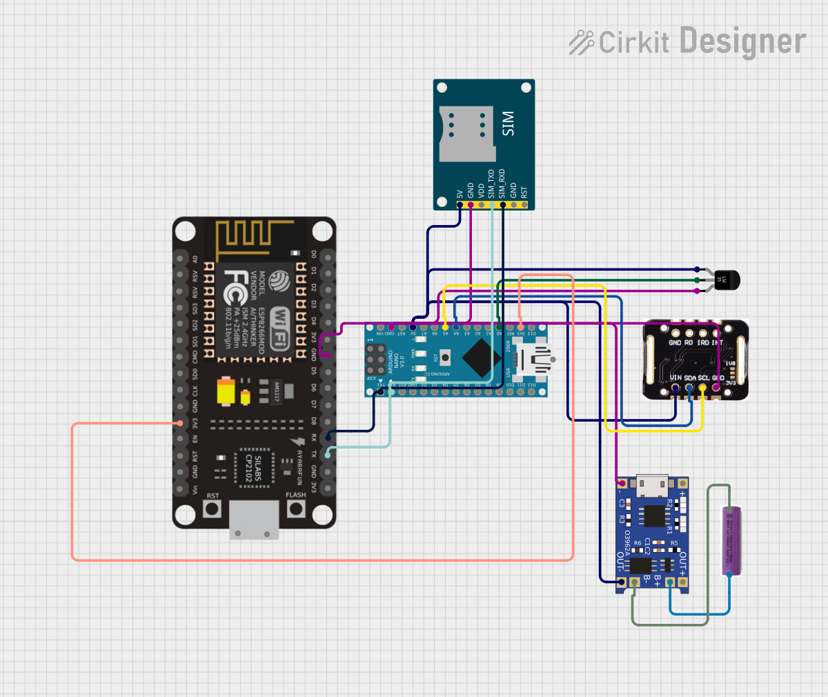
This circuit integrates a variety of components including an Arduino Nano, a MAX30102 pulse oximeter, an LM35 temperature sensor, an ESP-8266 WiFi module, a SIM800L GSM module, a TP4056 lithium battery charger, and a 3.7V battery. The Arduino Nano serves as the central microcontroller, interfacing with sensors and communication modules to collect data and transmit it. The MAX30102 is used for monitoring heart rate and blood oxygen levels, while the LM35 measures temperature. The ESP-8266 provides WiFi connectivity, and the SIM800L module enables GSM communication. The TP4056 ensures safe charging of the 3.7V battery, which powers the circuit.
Component List
Arduino Nano
- Microcontroller board based on the ATmega328P
- Features digital and analog I/O pins
- Provides serial communication via UART
MAX30102
- Pulse oximetry and heart-rate sensor
- Communicates with the Arduino Nano via I2C
Temperature Sensor (LM35)
- Analog temperature sensor with a linear output
- Provides temperature readings without the need for external calibration
ESP-8266 Controller
- WiFi module with integrated TCP/IP protocol stack
- Can be used for Internet connectivity and local networking
SIM800L GSM Module
- GSM/GPRS module for cellular communication
- Supports voice calls, SMS, and data transmission
TP4056
- Lithium battery charger with micro USB input
- Provides charge management and protection for single-cell lithium batteries
3.7V Battery
- Single-cell lithium-ion/polymer battery
- Provides power to the circuit
Wiring Details
Arduino Nano
D1/TXconnected to SIM800L GSM ModuleSIM_RXDand ESP-8266RXD0/RXconnected to SIM800L GSM ModuleSIM_TXDand ESP-8266TXGNDconnected to common ground net5Vconnected to 5V netA5connected to MAX30102SCLA4connected to MAX30102SDAA0connected to LM35Vout3V3connected to ESP-82663V3
MAX30102
VINconnected to 5V netSDAconnected to Arduino NanoA4SCLconnected to Arduino NanoA5GNDconnected to common ground net
Temperature Sensor (LM35)
+Vsconnected to 5V netVoutconnected to Arduino NanoA0GNDconnected to common ground net
ESP-8266 Controller
3V3connected to Arduino Nano3V3GNDconnected to common ground netRXconnected to Arduino NanoD1/TXTXconnected to Arduino NanoD0/RX
SIM800L GSM Module
5Vconnected to 5V netGNDconnected to common ground netSIM_TXDconnected to Arduino NanoD0/RXSIM_RXDconnected to Arduino NanoD1/TX
TP4056
B+connected to 3.7V battery+B-connected to 3.7V battery-OUT+connected to 5V netIN-connected to common ground net
3.7V Battery
+connected to TP4056B+-connected to TP4056B-
Documented Code
Arduino Nano Code (sketch.ino)
void setup() {
  // put your setup code here, to run once:

}

void loop() {
  // put your main code here, to run repeatedly:

}
Additional Notes (documentation.txt)
No additional code documentation provided.