Cirkit Designer
Your all-in-one circuit design IDE
Home /
Project Documentation
555 Timer-Based Oscilloscope Signal Generator

Circuit Documentation
Summary of the Circuit
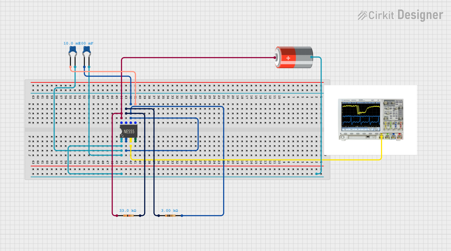
This circuit appears to be a basic timer or oscillator configuration using a 555 Timer IC. The 555 Timer IC is a versatile chip that can be used in various timing and pulse generation applications. The circuit includes a power source, capacitors, resistors, and an oscilloscope for monitoring the output signal. The absence of microcontroller code suggests that this circuit operates purely on analog principles, without digital control or processing.
Component List
Mixed Signal Oscilloscope
- Description: An oscilloscope used to observe the waveform outputs of the circuit.
- Purpose: To monitor and measure the signal generated by the 555 Timer IC.
5v Battery
- Description: A power source providing a stable 5V supply.
- Purpose: To power the 555 Timer IC and other components in the circuit.
Ceramic Capacitors
- Description: Two ceramic capacitors with different capacitance values.
- Purpose: To stabilize voltage and shape the timing characteristics of the 555 Timer IC.
- Properties:
- Capacitance: 0.01 Farads and 0.1 Farads.
555 Timer IC
- Description: An integrated circuit used for generating precise time delays or oscillation.
- Purpose: The core of the circuit, responsible for the timing and pulse generation.
Resistors
- Description: Two resistors with different resistance values.
- Purpose: To set the timing intervals for the 555 Timer IC and to limit current.
- Properties:
- Resistance: 33,000 Ohms and 3,000 Ohms.
Wiring Details
Mixed Signal Oscilloscope
- Connections:
- Pin 1 is connected to the 'Out' pin of the 555 Timer IC.
5v Battery
- Connections:
- '+' pin is connected to the 'VCC+' pin of the 555 Timer IC and one end of a 33,000 Ohms resistor.
- '-' pin is connected to the 'GND' pin of the 555 Timer IC and the negative pins of both ceramic capacitors.
Ceramic Capacitors
- Connections:
- 0.01 Farads Capacitor:
- One pin is connected to the 'CV' pin of the 555 Timer IC.
- The other pin is connected to the 'GND' pin of the 555 Timer IC.
- 0.1 Farads Capacitor:
- One pin is connected to the 'Th' and 'Trig' pins of the 555 Timer IC and one end of a 3,000 Ohms resistor.
- The other pin is connected to the 'GND' pin of the 555 Timer IC.
- 0.01 Farads Capacitor:
555 Timer IC
- Connections:
- 'VCC+' pin is connected to the '+' pin of the 5v Battery and one end of a 33,000 Ohms resistor.
- 'Dis' pin is connected to one end of a 33,000 Ohms resistor and one end of a 3,000 Ohms resistor.
- 'Th' and 'Trig' pins are interconnected and also connected to one pin of a 0.1 Farads capacitor and one end of a 3,000 Ohms resistor.
- 'CV' pin is connected to one pin of a 0.01 Farads capacitor.
- 'Rst' pin is not connected to any other components.
- 'Out' pin is connected to Pin 1 of the Mixed Signal Oscilloscope.
- 'GND' pin is connected to the '-' pin of the 5v Battery and the negative pins of both ceramic capacitors.
Resistors
- Connections:
- 33,000 Ohms Resistor:
- One end is connected to the '+' pin of the 5v Battery and the 'VCC+' pin of the 555 Timer IC.
- The other end is connected to the 'Dis' pin of the 555 Timer IC.
- 3,000 Ohms Resistor:
- One end is connected to the 'Dis' pin of the 555 Timer IC.
- The other end is connected to the 'Th' and 'Trig' pins of the 555 Timer IC and one pin of a 0.1 Farads capacitor.
- 33,000 Ohms Resistor:
Documented Code
There is no embedded code provided for this circuit as it does not include any programmable microcontrollers. The operation of the circuit is purely analog and based on the configuration of the 555 Timer IC and passive components.