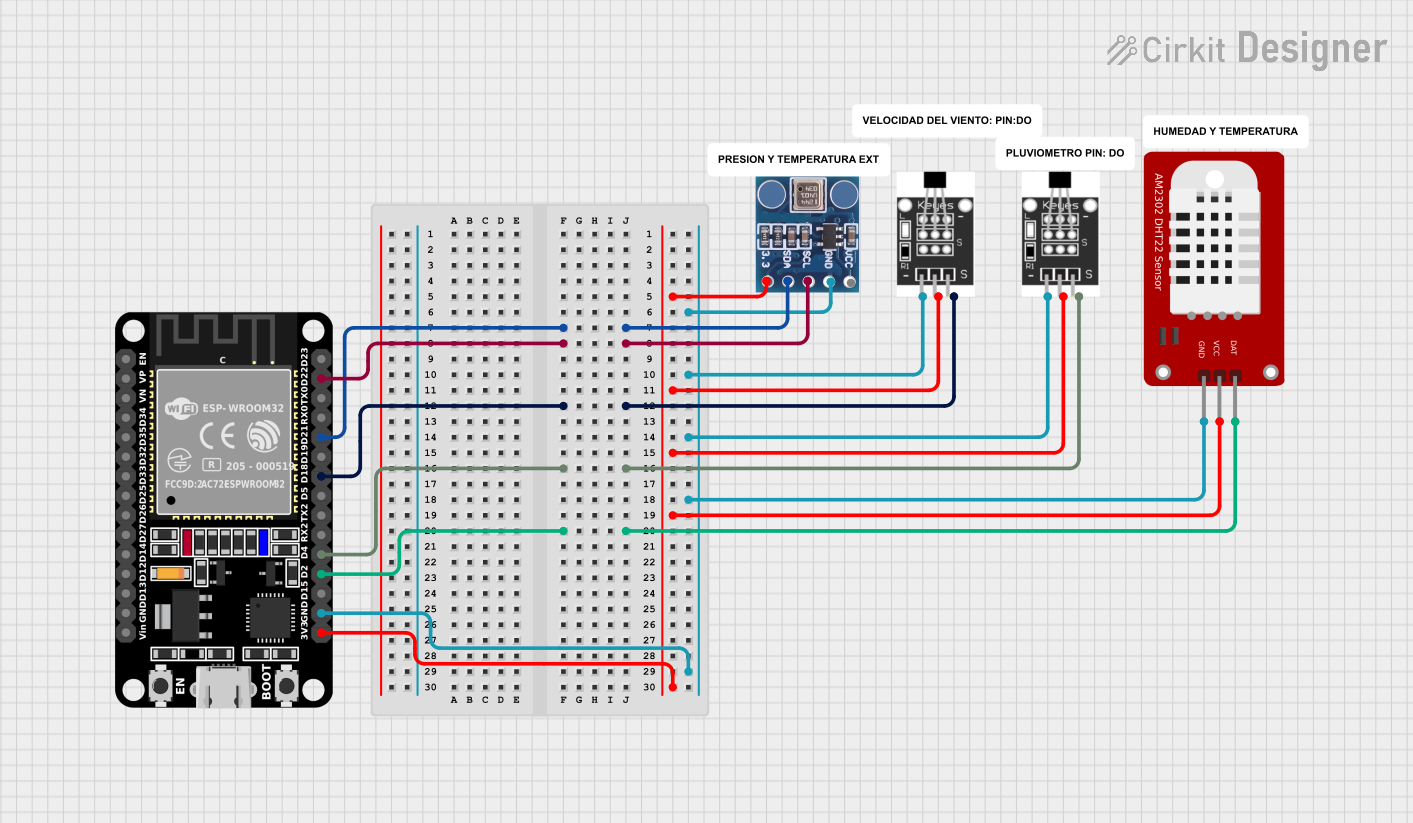
ESP32-Based Environmental Sensing Station with Dual Hall Sensors

Circuit Documentation
Summary of the Circuit
The circuit in question appears to be designed for environmental sensing and monitoring, utilizing an ESP32 microcontroller as the central processing unit. The ESP32 is interfaced with a DHT22 temperature and humidity sensor, a BMP180 barometric pressure sensor, and two Hall effect sensors for detecting magnetic fields. The ESP32 facilitates data communication and processing for these sensors. The circuit is powered through the ESP32's 3.3V pin, which is distributed to the other components. Ground connections are also shared among all components, ensuring a common reference point for all signals.
Component List
ESP32 (30 pin)
- Description: A microcontroller with Wi-Fi and Bluetooth capabilities, featuring a wide range of GPIO pins for interfacing with various sensors and peripherals.
- Pins: EN, VP, VN, D34, D35, D32, D33, D25, D26, D27, D14, D12, D13, GND, Vin, D23, D22, TX0, RX0, D21, D19, D18, D5, TX2, RX2, D4, D2, D15, 3V3
DHT22
- Description: A digital temperature and humidity sensor with a single data line for communication.
- Pins: GND, VCC, DAT
BMP180
- Description: A digital barometric pressure sensor that also provides temperature measurements, using I2C for communication.
- Pins: 3.3, SDA, SCL, GND, VCC
Hall Sensor
- Description: A sensor that detects the presence of a magnetic field, outputting a digital signal.
- Pins: -, +, S
Wiring Details
ESP32 (30 pin)
- D21 connected to BMP180 SDA
- D22 connected to BMP180 SCL
- D18 connected to Hall Sensor S (first instance)
- D4 connected to Hall Sensor S (second instance)
- D2 connected to DHT22 DAT
- 3V3 connected to BMP180 3.3, Hall Sensor + (both instances), and DHT22 VCC
- GND connected to BMP180 GND, Hall Sensor - (both instances), and DHT22 GND
DHT22
- DAT connected to ESP32 D2
- VCC connected to ESP32 3V3
- GND connected to ESP32 GND
BMP180
- SDA connected to ESP32 D21
- SCL connected to ESP32 D22
- 3.3 connected to ESP32 3V3
- GND connected to ESP32 GND
- VCC not explicitly connected (assumed to be connected to 3.3V)
Hall Sensor (first instance)
- S connected to ESP32 D18
- connected to ESP32 3V3
- connected to ESP32 GND
Hall Sensor (second instance)
- S connected to ESP32 D4
- connected to ESP32 3V3
- connected to ESP32 GND
Documented Code
No code was provided for the microcontrollers in the circuit. Typically, this section would include the embedded code written for the ESP32, detailing the setup and loop functions, libraries used, and any functions or routines for sensor data acquisition and processing. Since no code is available, it is recommended to develop firmware that initializes the I2C communication for the BMP180, sets up the digital pins for the DHT22 and Hall sensors, reads sensor data, and implements any required logic for the application.