Cirkit Designer
Your all-in-one circuit design IDE
Home /
Project Documentation
Arduino UNO Controlled Servomotor with RTC and I2C LCD Interface
Circuit Documentation
Summary of the Circuit
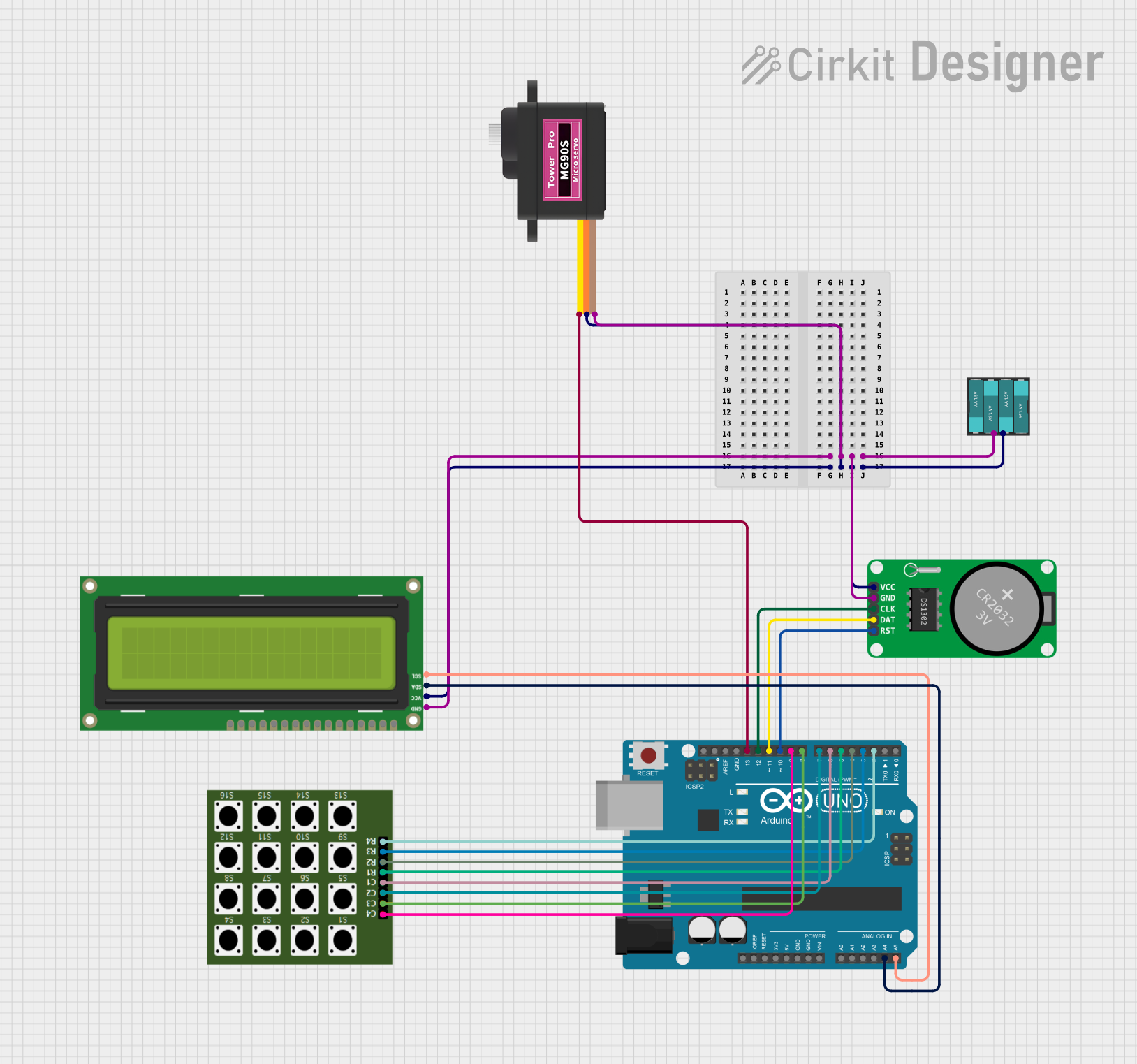
This circuit is designed to interface an Arduino UNO with a variety of peripherals including a 4×4 Keypad, an I2C LCD 16x2 Screen, a Real-Time Clock (RTC-DS1302), and a Servomotor MG90S. The Arduino UNO serves as the central processing unit, controlling the input from the keypad, displaying information on the LCD screen, keeping track of time with the RTC, and driving the servomotor based on the program logic. The battery provides power to the entire circuit.
Component List
Battery
- Description: Provides power to the circuit.
- Pins:
+(positive),-(negative)
4×4 Keypad
- Description: An input device with 16 keys arranged in a 4x4 matrix.
- Pins:
C3,C2,C4,C1,R1,R2,R3,R4
Arduino UNO
- Description: A microcontroller board based on the ATmega328P.
- Pins:
UNUSED,IOREF,Reset,3.3V,5V,GND,Vin,A0toA5,SCL,SDA,AREF,D13toD0
I2C LCD 16x2 Screen
- Description: A liquid crystal display capable of showing 2 lines of 16 characters each.
- Pins:
SCL,SDA,VCC (5V),GND,VDD,VO,RS,RW,E,D0toD7,BLA,BLK
RTC-DS1302
- Description: A real-time clock module for keeping track of the current time.
- Pins:
Vcc,GND,CLK,DAT,RST
Servomotor MG90S
- Description: A small and lightweight servo motor for precise angular movement.
- Pins:
SIG,VCC,GND
Wiring Details
Battery
- Connections:
+to VCC of Servomotor MG90S, RTC-DS1302, and I2C LCD 16x2 Screen-to GND of Servomotor MG90S, RTC-DS1302, and I2C LCD 16x2 Screen
4×4 Keypad
- Connections:
C3toD8on Arduino UNOC2toD7on Arduino UNOC4toD9on Arduino UNOC1toD6on Arduino UNOR1toD5on Arduino UNOR2toD4on Arduino UNOR3toD3on Arduino UNOR4toD2on Arduino UNO
Arduino UNO
- Connections:
A5toSCLon I2C LCD 16x2 ScreenA4toSDAon I2C LCD 16x2 ScreenD13toSIGon Servomotor MG90SD12toCLKon RTC-DS1302D11toDATon RTC-DS1302D10toRSTon RTC-DS1302
I2C LCD 16x2 Screen
- Connections:
SCLtoA5on Arduino UNOSDAtoA4on Arduino UNOVCC (5V)to+on BatteryGNDto-on Battery
RTC-DS1302
- Connections:
Vccto+on BatteryGNDto-on BatteryCLKtoD12on Arduino UNODATtoD11on Arduino UNORSTtoD10on Arduino UNO
Servomotor MG90S
- Connections:
SIGtoD13on Arduino UNOVCCto+on BatteryGNDto-on Battery
Documented Code
Arduino UNO Code (sketch.ino)
void setup() {
  // put your setup code here, to run once:

}

void loop() {
  // put your main code here, to run repeatedly:

}
Note: The provided code is a template and does not contain any specific logic. It needs to be filled in with the actual code to control the components as per the circuit's requirements.