
LDR and Buzzer-Based Light Detection Alarm with Battery Power
View and Edit Project In Cirkit Designer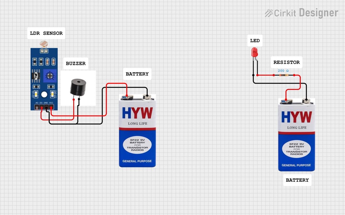
Circuit Documentation
Summary
This circuit consists of a Light Dependent Resistor (LDR), a buzzer, two 9V batteries, a red LED, and a resistor. The circuit is designed to activate the buzzer when the LDR detects a certain level of light. Additionally, the LED is powered through a resistor to limit the current.
Component List
LDR (Light Dependent Resistor)
- Pins: A0, D0, GND, VCC
- Description: A sensor that changes its resistance based on the amount of light it is exposed to.
Buzzer
- Pins: +, GND
- Description: An audio signaling device that emits sound when powered.
9V Battery
- Pins: +, -
- Description: A power source providing 9 volts of DC power.
LED: Two Pin (red)
- Pins: cathode, anode
- Description: A light-emitting diode that emits red light when powered.
Resistor
- Pins: pin1, pin2
- Description: A passive electrical component that limits the current flow.
- Properties: Resistance: 200 Ohms
Wiring Details
LDR (Light Dependent Resistor)
- D0 is connected to the + pin of the buzzer.
- GND is connected to the GND pin of the buzzer and the - pin of the 9V battery.
- VCC is connected to the + pin of the 9V battery.
Buzzer
- + is connected to the D0 pin of the LDR.
- GND is connected to the GND pin of the LDR and the - pin of the 9V battery.
9V Battery (First)
- + is connected to the VCC pin of the LDR.
- - is connected to the GND pin of the LDR and the GND pin of the buzzer.
LED: Two Pin (red)
- cathode is connected to the - pin of the second 9V battery.
- anode is connected to pin1 of the resistor.
Resistor
- pin1 is connected to the anode pin of the LED.
- pin2 is connected to the + pin of the second 9V battery.
9V Battery (Second)
- + is connected to pin2 of the resistor.
- - is connected to the cathode pin of the LED.
Code
There is no microcontroller code associated with this circuit.
This documentation provides a comprehensive overview of the circuit, including a summary, detailed component list, wiring details, and code (if any). This should help in understanding and replicating the circuit effectively.