
Arduino Due and ADS1115 Battery-Powered Differential Voltage Sensor
View and Edit Project In Cirkit Designer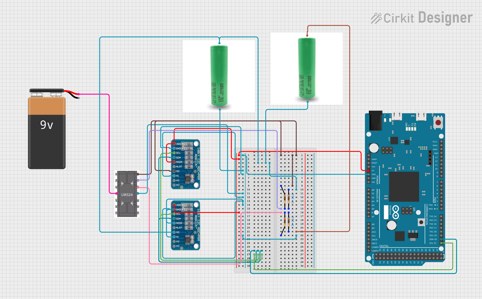
Circuit Documentation
Summary
This circuit involves an Arduino Due microcontroller interfacing with two ADS1115 analog-to-digital converters, an LM324 operational amplifier, several resistors, and power sources including a 9V battery and two 21700 lithium-ion batteries. The Arduino Due reads differential voltages from the ADS1115 modules and processes the data accordingly.
Component List
Arduino Due
- Description: A microcontroller board based on the Atmel SAM3X8E ARM Cortex-M3 CPU.
- Pins: A0-A11, DAC0, DAC1, CANRX, CANTX, D0-D53, IOREF, MASTER-RESET, 5V, GND, VIN, AREF, SDA1, SCL1, unused.
21700 Lithium-Ion Battery
- Description: A rechargeable lithium-ion battery.
- Pins: +, -.
ADS1115
- Description: A 16-bit analog-to-digital converter with I2C interface.
- Pins: VDD, GND, SCL, SDA, ADDR, ALRT, A0, A1, A2, A3.
LM324
- Description: A quad operational amplifier.
- Pins: out1, + in 1, VCC, + in 2, - in 2, out 2, out 3, - in 3, + in 3, GND, + in 4, - in 4, out 4, - in 1.
9V Battery
- Description: A standard 9V battery.
- Pins: +, -.
Resistor (200 Ohms)
- Description: A resistor with a resistance of 200 Ohms.
- Pins: pin1, pin2.
Wiring Details
Arduino Due
- 5V connected to VDD of both ADS1115 modules.
- GND connected to:
- GND of both ADS1115 modules.
- GND of LM324.
- - of one 21700 LI battery.
- D20/SDA3 connected to SDA of both ADS1115 modules.
- D21/SCL3 connected to SCL of both ADS1115 modules.
21700 Lithium-Ion Battery
- + of one battery connected to pin2 of a resistor.
- - of one battery connected to GND of Arduino Due.
- + of the other battery connected to pin1 of a resistor.
- - of the other battery connected to pin1 of another resistor.
ADS1115
- VDD connected to 5V of Arduino Due.
- GND connected to GND of Arduino Due.
- SDA connected to D20/SDA3 of Arduino Due.
- SCL connected to D21/SCL3 of Arduino Due.
- ADDR of one module connected to GND.
- ADDR of the other module connected to 5V.
- A0 of one module connected to pin1 of a resistor.
- A0 of the other module connected to pin1 of another resistor.
- A1 of both modules connected to GND.
LM324
- VCC connected to + of 9V battery.
- GND connected to GND of Arduino Due.
- out 4 connected to pin1 of a resistor.
- - in 4 connected to pin2 of two resistors.
- + in 4 connected to pin1 of two resistors.
9V Battery
- + connected to VCC of LM324.
- - not connected.
Resistors
- Resistor 1:
- pin1 connected to out 4 of LM324.
- pin2 connected to pin2 of another resistor and - in 4 of LM324.
- Resistor 2:
- pin1 connected to A0 of one ADS1115 module.
- pin2 connected to pin2 of another resistor and - in 4 of LM324.
- Resistor 3:
- pin1 connected to pin1 of another resistor and + in 4 of LM324.
- pin2 connected to + of one 21700 LI battery.
- Resistor 4:
- pin1 connected to pin1 of another resistor and + in 4 of LM324.
- pin2 connected to GND of Arduino Due.
Code Documentation
Arduino Due Code
#include <Adafruit_ADS1X15.h>
#include <Wire.h>

const int sensorPin = A0;
int numReadings = 10;

// 두 개의 ADS1115 모듈 객체 생성
Adafruit_ADS1115 ads1115_1;  // 첫 번째 모듈, 기본 주소 0x48
Adafruit_ADS1115 ads1115_2;  // 두 번째 모듈, 주소 0x49

void setup(void) {
  Serial.begin(9600);
  Serial.println("Hello!");

  // 첫 번째 ADS1115 모듈 초기화
  if (!ads1115_1.begin(0x48)) {
    Serial.println("첫 번째 ADS1115 통신 실패. I2C 주소 또는 연결을 확인하세요.");
    while (1);
  }

  // 두 번째 ADS1115 모듈 초기화
  if (!ads1115_2.begin(0x49)) {
    Serial.println("두 번째 ADS1115 통신 실패. I2C 주소 또는 연결을 확인하세요.");
    while (1);
  }

  ads1115_1.setGain(GAIN_TWOTHIRDS);  // 첫 번째 모듈 Gain 설정
  ads1115_2.setGain(GAIN_TWOTHIRDS);  // 두 번째 모듈 Gain 설정
  Serial.println("ADC Range: +/- 6.144V (1 bit = 0.1875mV)");
}

void loop(void) {
  int16_t adc1_diff, adc2_diff;

  // 첫 번째 모듈에서 AIN0과 AIN1 간 차동 전압 읽기
  adc1_diff = ads1115_1.readADC_Differential_0_1();
  Serial.print("첫 번째 모듈 차동 전압 (AIN0 - AIN1): ");
  Serial.print(adc1_diff * 0.1875 / 1000);  // 1 bit = 0.1875 mV
  Serial.println(" V");

  // 두 번째 모듈에서 AIN0과 AIN1 간 차동 전압 읽기
  adc2_diff = ads1115_2.readADC_Differential_0_1();
  Serial.print("두 번째 모듈 차동 전압 (AIN0 - AIN1): ");
  Serial.print(adc2_diff * 0.1875 / 1000);  // 1 bit = 0.1875 mV
  Serial.println(" V");

  delay(2000);
}
21700 LI Battery Code
void setup() {
  // put your setup code here, to run once:
}

void loop() {
  // put your main code here, to run repeatedly:
}
ADS1115 Code
void setup() {
  // put your setup code here, to run once:
}

void loop() {
  // put your main code here, to run repeatedly:
}
This documentation provides a comprehensive overview of the circuit, including a summary, detailed component list, wiring details, and the code used in the microcontrollers.