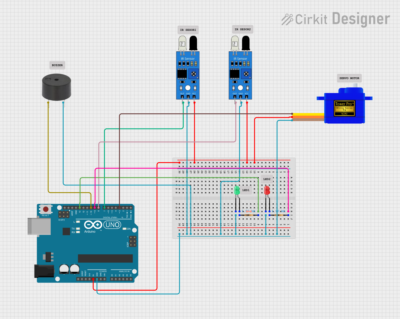
Arduino UNO Based IR Sensor Alarm with Servo Control and Indicator LEDs

Circuit Documentation
Summary of the Circuit
This circuit is designed around an Arduino UNO microcontroller and includes various peripherals such as IR sensors, a buzzer, a servomotor, and LEDs. The circuit is likely intended for object detection or proximity sensing, indicated by the use of IR sensors. Upon detection of an object, the circuit can provide visual signals through LEDs, auditory signals through a buzzer, and physical movement using a servomotor. The Arduino UNO controls these components based on the input from the IR sensors.
Component List
Arduino UNO
- Microcontroller board based on the ATmega328P
- It has 14 digital input/output pins, 6 analog inputs, a 16 MHz quartz crystal, a USB connection, a power jack, an ICSP header, and a reset button.
IR Sensor
- An infrared sensor capable of detecting obstacles and measuring distances.
- It has an output pin that connects to a digital input on the Arduino.
Buzzer
- An electromechanical component that can produce sound when powered.
- Typically used for audible alerts or alarms.
Servomotor SG90
- A small and lightweight servo motor capable of precise control.
- It can be positioned at various angles from 0 to 180 degrees.
LED: Two Pin (Red and Green)
- Light Emitting Diodes that emit red and green light, respectively.
- Used as visual indicators in the circuit.
Resistor
- A passive two-terminal electrical component that implements electrical resistance as a circuit element.
- In this circuit, resistors are likely used to limit current to the LEDs.
Wiring Details
Arduino UNO
- Digital Pin 9 (D9): Connected to one end of a resistor, which connects to the red LED.
- Digital Pin 13 (D13): Connected to one end of a resistor, which connects to the green LED.
- Digital Pin 10 (D10): Connected to the buzzer.
- Digital Pin 8 (D8): Connected to the output of one IR sensor.
- Digital Pin 7 (D7): Connected to the output of another IR sensor.
- Digital Pin 3 (D3): Connected to the signal pin of the servomotor.
- 5V Pin: Powers the servomotor and both IR sensors.
- GND Pin: Common ground for the servomotor, IR sensors, buzzer, and LEDs.
IR Sensor
- Out: Connected to digital pins D7 and D8 on the Arduino for object detection.
- GND: Connected to the ground.
- VCC: Connected to the 5V supply from the Arduino.
Buzzer
- PIN: Connected to digital pin D10 on the Arduino.
- GND: Connected to the ground.
Servomotor SG90
- SIG: Connected to digital pin D3 on the Arduino.
- VCC: Powered by the 5V supply from the Arduino.
- GND: Connected to the ground.
LED: Two Pin (Red and Green)
- Cathode (Red and Green): Connected to the ground through a common ground net.
- Anode (Red): Connected to digital pin D13 on the Arduino through a resistor.
- Anode (Green): Connected to digital pin D9 on the Arduino through a resistor.
Resistor
- Pin1 (for both resistors): Connected to the anodes of the red and green LEDs, respectively.
- Pin2 (for both resistors): Connected to digital pins D13 and D9 on the Arduino, respectively.
Documented Code
#include<Servo.h>
Servo myservo;
const int irSensorPin1 = 7;
const int irSensorPin2 = 8;
const int buzzer = 10;

const int ledPin1 = 13;
const int ledPin2 = 9;
void setup() {
  pinMode(irSensorPin1, INPUT);
  pinMode(irSensorPin2, INPUT);
  pinMode(ledPin1, OUTPUT);
  pinMode(ledPin2, OUTPUT);
  pinMode(buzzer,OUTPUT);
  myservo.attach(3);
  Serial.begin(9600);
}

void loop() {
  int sensorValue1 = digitalRead(irSensorPin1);
  Serial.println(sensorValue1);
  int sensorValue2 = digitalRead(irSensorPin2);
  Serial.println(sensorValue2);
  if (sensorValue1 == LOW) {
    digitalWrite(ledPin1, HIGH);
    digitalWrite(ledPin2, LOW);
    myservo.write(90);
    noTone(buzzer);
    delay(1000);
  }
  if (sensorValue2 == LOW) {
    digitalWrite(ledPin1, LOW);
    digitalWrite(ledPin2, HIGH);
    myservo.write(0);
    tone(buzzer,1000);
    delay(1000);
  }
  delay(1000);
}
This code is designed to read the output from two IR sensors connected to digital pins D7 and D8. Depending on which sensor detects an object (signaled by a LOW reading), the Arduino will turn on a red or green LED, move the servomotor to a specific position, and either sound the buzzer or not. The servomotor is attached to pin D3, and the buzzer is controlled via pin D10. The LEDs are connected to pins D13 and D9 through resistors. Serial output is used for debugging purposes.