Cirkit Designer
Your all-in-one circuit design IDE
Home /
Project Documentation
Arduino UNO Controlled Multi-Color LED Array
Circuit Documentation
Summary of the Circuit
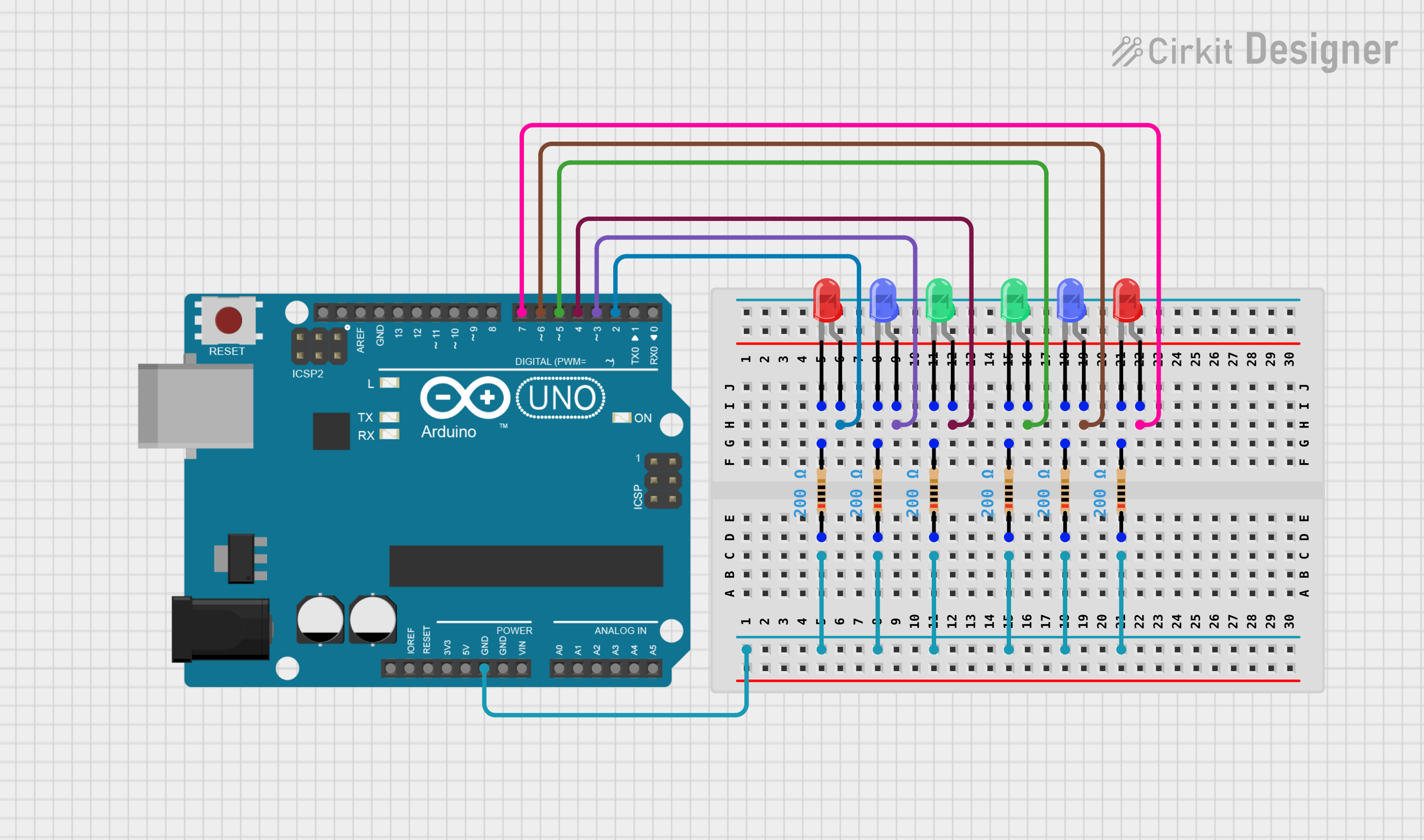
This circuit is designed around an Arduino UNO microcontroller and includes a series of LEDs (Light Emitting Diodes) of different colors (red, blue, and green). Each LED is connected to a digital output pin on the Arduino UNO through a current-limiting resistor. The purpose of this circuit is likely to demonstrate basic digital output control, such as blinking or pattern display, using the Arduino UNO.
Component List
Arduino UNO
- Description: A microcontroller board based on the ATmega328P.
- Pins: UNUSED, IOREF, Reset, 3.3V, 5V, GND, Vin, A0-A5, SCL, SDA, AREF, D0-D13
LED: Two Pin (red)
- Description: A red light-emitting diode.
- Pins: cathode, anode
LED: Two Pin (blue)
- Description: A blue light-emitting diode.
- Pins: cathode, anode
LED: Two Pin (green)
- Description: A green light-emitting diode.
- Pins: cathode, anode
Resistor
- Description: A resistor with a resistance value of 200 Ohms.
- Pins: pin1, pin2
Wiring Details
Arduino UNO
- GND is connected to the common cathode connection of all resistors.
- Digital pins D2, D3, D4, D5, D6, and D7 are connected to the anodes of the red, blue, and green LEDs through their respective resistors.
LED: Two Pin (red)
- Anode is connected to Arduino UNO digital pin (D2 or D7).
- Cathode is connected to a 200 Ohm resistor.
LED: Two Pin (blue)
- Anode is connected to Arduino UNO digital pin (D3 or D6).
- Cathode is connected to a 200 Ohm resistor.
LED: Two Pin (green)
- Anode is connected to Arduino UNO digital pin (D4 or D5).
- Cathode is connected to a 200 Ohm resistor.
Resistor
- One pin (pin2) is connected to the cathode of an LED.
- The other pin (pin1) is connected to the common ground net that ties all resistors together and then to the Arduino UNO GND pin.
Documented Code
Arduino UNO Microcontroller Code (sketch.ino)
void setup() {
  // put your setup code here, to run once:

}

void loop() {
  // put your main code here, to run repeatedly:

}
This code is a template and does not contain any functionality. To control the LEDs, you would need to configure the digital pins connected to the LEDs as outputs in the setup() function using pinMode(). Then, in the loop() function, you would toggle the pins high and low using digitalWrite() to turn the LEDs on and off.
Additional Notes
- The provided code does not include any specific functionality for the LEDs.
- The circuit appears to be set up for a basic LED control exercise, but the code to do so is not included in the provided inputs.
- The
documentation.txtfile is mentioned but contains no content.