Cirkit Designer
Your all-in-one circuit design IDE
Home /
Project Documentation
Arduino UNO Line Following Robot with L298N Motor Driver and Battery Power
Circuit Documentation
Summary
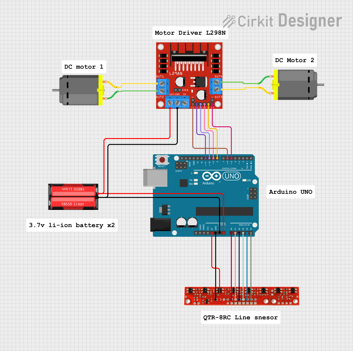
This document provides a detailed overview of a line-following robot circuit. The robot uses an Arduino UNO microcontroller to read values from a line sensor array and control two DC motors via an L298N motor driver. The robot is powered by a 18650 Li-Ion battery.
Component List
Arduino UNO
- Description: Microcontroller board based on the ATmega328P.
- Pins: UNUSED, IOREF, Reset, 3.3V, 5V, GND, Vin, A0, A1, A2, A3, A4, A5, SCL, SDA, AREF, D13, D12, D11, D10, D9, D8, D7, D6, D5, D4, D3, D2, D1, D0
Line Sensor
- Description: Sensor array used to detect lines on the ground.
- Pins: 8, 7, 6, 5, 4, 3, 2, 1, +5v, GND
L298N DC Motor Driver
- Description: Dual H-Bridge motor driver for controlling DC motors.
- Pins: OUT1, OUT2, 12V, GND, 5V, OUT3, OUT4, 5V-ENA-JMP-I, 5V-ENA-JMP-O, +5V-J1, +5V-J2, ENA, IN1, IN2, IN3, IN4, ENB
DC Motor (Motor 1)
- Description: Standard DC motor.
- Pins: pin 1, pin 2
DC Motor (Motor 2)
- Description: Standard DC motor.
- Pins: pin 1, pin 2
18650 Li-Ion Battery
- Description: Rechargeable lithium-ion battery.
- Pins: Positive, Negative
Wiring Details
Arduino UNO
- 5V to Line Sensor +5v
- GND to Line Sensor GND
- GND to L298N DC Motor Driver GND
- GND to 18650 Li-Ion Battery Negative
- Vin to L298N DC Motor Driver 12V
- Vin to 18650 Li-Ion Battery Positive
- A0 to Line Sensor 2
- A1 to Line Sensor 3
- A2 to Line Sensor 4
- A3 to Line Sensor 5
- A4 to Line Sensor 6
- A5 to Line Sensor 7
- D11 to L298N DC Motor Driver IN1
- D10 to L298N DC Motor Driver IN2
- D9 to L298N DC Motor Driver IN3
- D8 to L298N DC Motor Driver IN4
- D6 to L298N DC Motor Driver ENA
- D5 to L298N DC Motor Driver ENB
Line Sensor
- +5v to Arduino UNO 5V
- GND to Arduino UNO GND
- 2 to Arduino UNO A0
- 3 to Arduino UNO A1
- 4 to Arduino UNO A2
- 5 to Arduino UNO A3
- 6 to Arduino UNO A4
- 7 to Arduino UNO A5
L298N DC Motor Driver
- GND to Arduino UNO GND
- GND to 18650 Li-Ion Battery Negative
- 12V to Arduino UNO Vin
- 12V to 18650 Li-Ion Battery Positive
- IN1 to Arduino UNO D11
- IN2 to Arduino UNO D10
- IN3 to Arduino UNO D9
- IN4 to Arduino UNO D8
- ENA to Arduino UNO D6
- ENB to Arduino UNO D5
- OUT1 to DC Motor (Motor 1) pin 2
- OUT2 to DC Motor (Motor 1) pin 1
- OUT3 to DC Motor (Motor 2) pin 2
- OUT4 to DC Motor (Motor 2) pin 1
DC Motor (Motor 1)
- pin 2 to L298N DC Motor Driver OUT1
- pin 1 to L298N DC Motor Driver OUT2
DC Motor (Motor 2)
- pin 2 to L298N DC Motor Driver OUT3
- pin 1 to L298N DC Motor Driver OUT4
18650 Li-Ion Battery
- Negative to L298N DC Motor Driver GND
- Negative to Arduino UNO GND
- Positive to L298N DC Motor Driver 12V
- Positive to Arduino UNO Vin
Code Documentation
/*
 * Arduino-Controlled Line Following Robot with Dual DC Motors and L298N Driver
 * This code reads values from a line sensor array and controls two DC motors
 * via an L298N motor driver to follow a line.
 */

// Pin definitions
const int lineSensorPins[] = {A0, A1, A2, A3, A4, A5};
const int motorEnablePins[] = {5, 6};
const int motorControlPins[] = {8, 9, 10, 11};

void setup() {
  // Initialize line sensor pins
  for (int i = 0; i < 6; i++) {
    pinMode(lineSensorPins[i], INPUT);
  }
  // Initialize motor control pins
  for (int i = 0; i < 4; i++) {
    pinMode(motorControlPins[i], OUTPUT);
  }
  // Initialize motor enable pins
  for (int i = 0; i < 2; i++) {
    pinMode(motorEnablePins[i], OUTPUT);
  }
  // Enable motors
  digitalWrite(motorEnablePins[0], HIGH);
  digitalWrite(motorEnablePins[1], HIGH);
}

void loop() {
  int sensorValues[6];
  // Read sensor values
  for (int i = 0; i < 6; i++) {
    sensorValues[i] = analogRead(lineSensorPins[i]);
  }
  // Determine motor actions based on sensor values
  if (sensorValues[0] < 500 && sensorValues[5] < 500) {
    // Move forward
    moveForward();
  } else if (sensorValues[0] < 500) {
    // Turn left
    turnLeft();
  } else if (sensorValues[5] < 500) {
    // Turn right
    turnRight();
  } else {
    // Stop
    stopMotors();
  }
}

void moveForward() {
  digitalWrite(motorControlPins[0], HIGH);
  digitalWrite(motorControlPins[1], LOW);
  digitalWrite(motorControlPins[2], HIGH);
  digitalWrite(motorControlPins[3], LOW);
}

void turnLeft() {
  digitalWrite(motorControlPins[0], LOW);
  digitalWrite(motorControlPins[1], HIGH);
  digitalWrite(motorControlPins[2], HIGH);
  digitalWrite(motorControlPins[3], LOW);
}

void turnRight() {
  digitalWrite(motorControlPins[0], HIGH);
  digitalWrite(motorControlPins[1], LOW);
  digitalWrite(motorControlPins[2], LOW);
  digitalWrite(motorControlPins[3], HIGH);
}

void stopMotors() {
  digitalWrite(motorControlPins[0], LOW);
  digitalWrite(motorControlPins[1], LOW);
  digitalWrite(motorControlPins[2], LOW);
  digitalWrite(motorControlPins[3], LOW);
}
This code initializes the line sensor and motor control pins, reads sensor values, and controls the motors to follow a line based on the sensor readings. The robot moves forward, turns left, turns right, or stops based on the sensor values.