
Circuit Documentation
Summary
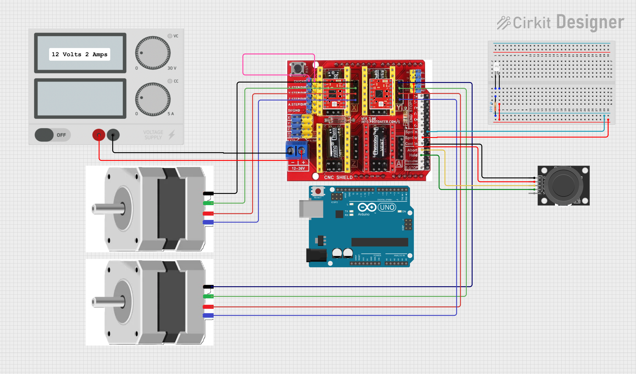
This circuit is designed to control a CNC machine using a combination of stepper motors, a joystick module, and an Arduino UNO microcontroller. The CNC Shield V3 is used to interface the stepper motors and joystick with the Arduino. The circuit also includes an LED with a current-limiting resistor and a power supply to provide the necessary voltage.
Component List
NEMA23 Stepper Motor
- Pins: A+, A-, B+, B-
- Description: Stepper motor used for precise control of the CNC machine's movements.
KY-023 Dual Axis Joystick Module
- Pins: GND, +5V, VRx, VRy, SW
- Description: Joystick module used for manual control of the CNC machine.
CNC Shield V3 Engraving Machine Expansion Board
- Pins: EN, GND, x.Step, DIR, Y.Step, Z.Step, A.Step, 5V, COM, V+, End Stop X-, End Stop Z+, End Stop Z-, End Stop Y+, End Stop Y-, SpnEN, SpnDir, CoolEn, Abort, Hold, Resume, E-Stop, Y.Motor A+, Y.Motor A-, Y.Motor B+, Y.Motor B-, RST, SDA, SCL, RX, TX, 3V3, X.Motor A+, X.Motor A-, X.Motor B+, X.Motor B-, Z.Motor A+, Z.Motor A-, Z.Motor B+, Z.Motor B-, A.Motor A+, A.Motor A-, A.Motor B+, A.Motor B-, Enable, MS1, MS2, MS3, RESET, Sleep, Step, Direction, VDD, 1B, 1A, 2A, 2B, VMOT, M0, M1, M2, d12, A Drive Step and Direction, Z Drive Module Setp D4, Y Drive Module Setp D3, X Drive Module Setp D2, Set X Drive Module Dir D5, Set Y Drive Module Dir D6, Set Z Drive Module DIR d7, D13
- Description: Shield used to interface stepper motors and other components with the Arduino.
Power Supply
- Pins: +, -
- Description: Provides the necessary voltage for the circuit.
Resistor
- Pins: pin1, pin2
- Description: 220 Ohms resistor used to limit the current through the LED.
LED: Two Pin (white)
- Pins: cathode, anode
- Description: White LED used as an indicator.
A988 DRIVER
- Pins: VMOT, GND, 2B, 2A, 1A, 1B, VDD, EN, MS1, MS2, MS3, RST, SLP, STEP, DIR
- Description: Stepper motor driver used to control the stepper motors.
Arduino UNO
- Pins: UNUSED, IOREF, Reset, 3.3V, 5V, GND, Vin, A0, A1, A2, A3, A4, A5, SCL, SDA, AREF, D13, D12, D11, D10, D9, D8, D7, D6, D5, D4, D3, D2, D1, D0
- Description: Microcontroller used to control the entire circuit.
Wiring Details
NEMA23 Stepper Motor
- A+ connected to Y.Motor A+ on CNC Shield V3
- A- connected to Y.Motor A- on CNC Shield V3
- B+ connected to Y.Motor B+ on CNC Shield V3
- B- connected to Y.Motor B- on CNC Shield V3
NEMA23 Stepper Motor
- A+ connected to X.Motor A+ on CNC Shield V3
- A- connected to X.Motor A- on CNC Shield V3
- B+ connected to X.Motor B+ on CNC Shield V3
- B- connected to X.Motor B- on CNC Shield V3
KY-023 Dual Axis Joystick Module
- GND connected to GND on CNC Shield V3
- +5V connected to 5V on CNC Shield V3
- VRx connected to Abort on CNC Shield V3
- VRy connected to Hold on CNC Shield V3
CNC Shield V3 Engraving Machine Expansion Board
- EN connected to GND on CNC Shield V3
- GND connected to pin1 on Resistor
- SpnDir connected to anode on LED
- COM connected to - on Power Supply
- V+ connected to + on Power Supply
Resistor
- pin2 connected to cathode on LED
LED: Two Pin (white)
- anode connected to SpnDir on CNC Shield V3
- cathode connected to pin2 on Resistor
Power Supply
- - connected to COM on CNC Shield V3
- + connected to V+ on CNC Shield V3
Documented Code
Arduino UNO Code
void setup() {
  // put your setup code here, to run once:

}

void loop() {
  // put your main code here, to run repeatedly:

}
This code is a basic template for the Arduino UNO. The setup function is used to initialize any settings or configurations, and the loop function contains the main code that runs repeatedly.