Arduino UNO Based Obstacle Avoiding Robot with IR Sensors and L298N Motor Driver
Circuit Documentation
Summary
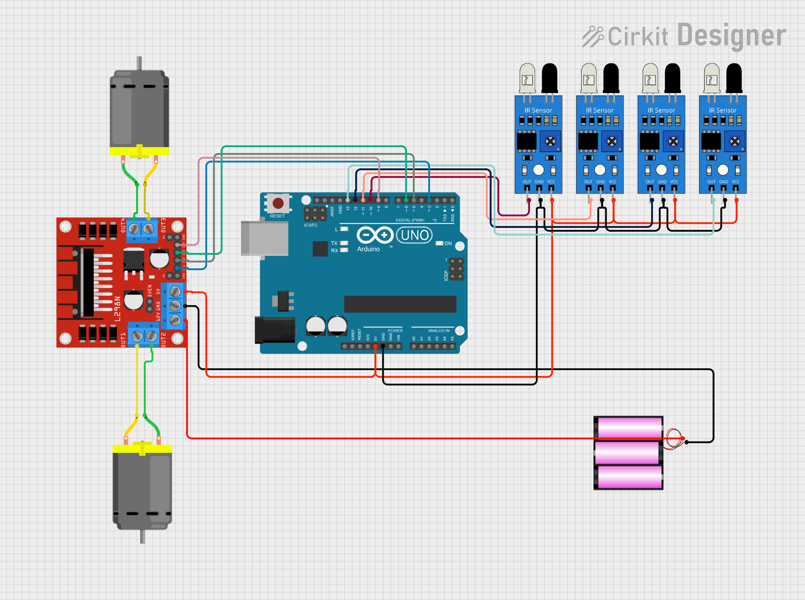
This circuit is designed to control an obstacle-avoiding robot using an Arduino UNO microcontroller. The robot utilizes four infrared (IR) sensors to detect obstacles and two DC motors for movement. The motors are driven by an L298N DC motor driver, which is controlled by the Arduino UNO. The IR sensors provide input to the Arduino, which then processes the data and sends commands to the motor driver to maneuver the robot accordingly. A 12V battery is used to power the motor driver, which also supplies 5V to the Arduino and the IR sensors.
Component List
Arduino UNO
- Microcontroller board based on the ATmega328P
- Used for processing sensor inputs and controlling the motor driver
Battery 12V
- Provides power to the circuit
- 12V output used to power the L298N motor driver
IR Sensors (4x)
- Detects obstacles in the path of the robot
- Each sensor has an output, ground, and VCC pin
L298N DC Motor Driver
- Interfaces between the Arduino and the motors
- Drives the two DC motors based on commands from the Arduino
DC Motors (2x)
- Provide movement to the robot
- Controlled by the L298N motor driver
Wiring Details
Arduino UNO
- 5V pin connected to the 5V supply net, powering the IR sensors and the L298N motor driver
- GND pin connected to the ground net, providing a common ground for the circuit
- Digital pins D3, D5, D6, and D9 connected to the L298N motor driver inputs (IN1, IN2, IN3, IN4)
- Digital pins D10, D11, D12, and D13 connected to the outputs of the IR sensors
Battery 12V
- Positive (+) pin connected to the 12V input of the L298N motor driver
- Negative (-) pin connected to the ground net of the circuit
IR Sensors
- VCC pins connected to the 5V supply net
- GND pins connected to the ground net
- OUT pins connected to the Arduino digital pins D10, D11, D12, and D13
L298N DC Motor Driver
- 5V pin connected to the 5V supply net
- GND pin connected to the ground net
- 12V pin connected to the positive (+) pin of the 12V battery
- IN1, IN2, IN3, and IN4 pins connected to the Arduino digital pins D3, D5, D6, and D9
- OUT1 and OUT2 pins connected to one DC motor
- OUT3 and OUT4 pins connected to the other DC motor
DC Motors
- Each motor has two pins connected to the OUT pins of the L298N motor driver
Documented Code
/*
Obstacle Avoiding Arduino Robot Sketch
by Roland
www.teachmemicro.com/arduino-robot-obstacle-avoiding
*/

// Motor Driver Pins
int Motor_INA = 3;
int Motor_INB = 5;
int Motor_INC = 6;
int Motor_IND = 9;

// Sensor Pins
int Sensor_IN1 = 10;
int Sensor_IN2 = 11;
int Sensor_IN3 = 12;
int Sensor_IN4 = 13;

void setup() {
  // Initialize motor driver pins
  pinMode(Motor_INA, OUTPUT);
  pinMode(Motor_INB, OUTPUT);
  pinMode(Motor_INC, OUTPUT);
  pinMode(Motor_IND, OUTPUT);

  // Initialize sensor pins
  pinMode(Sensor_IN1, INPUT);
  pinMode(Sensor_IN2, INPUT);
  pinMode(Sensor_IN3, INPUT);
  pinMode(Sensor_IN4, INPUT);

  // Start Serial Communication
  Serial.begin(9600);
}

void goReverse(){
  analogWrite(Motor_INA, 0);
  analogWrite(Motor_INB, 50);
  analogWrite(Motor_INC, 0);
  analogWrite(Motor_IND, 50);
  Serial.println("Moving Reverse");
  delay(500);
}

void goRight(){
  analogWrite(Motor_INA, 0);
  analogWrite(Motor_INB, 0);
  analogWrite(Motor_INC, 50);
  analogWrite(Motor_IND, 0);
  Serial.println("Turning Right");
}

void goLeft(){
  analogWrite(Motor_INA, 50);
  analogWrite(Motor_INB, 0);
  analogWrite(Motor_INC, 0);
  analogWrite(Motor_IND, 0);
  Serial.println("Turning Left");
}

void stopBot(){
  analogWrite(Motor_INA, 0);
  analogWrite(Motor_INB, 0);
  analogWrite(Motor_INC, 0);
  analogWrite(Motor_IND, 0);
  Serial.println("Stopping");
}

void goStraight(){
  analogWrite(Motor_INA, 50);
  analogWrite(Motor_INB, 0);
  analogWrite(Motor_INC, 50);
  analogWrite(Motor_IND, 0);
  Serial.println("Moving Straight");
}

void loop() {
  // Read sensor values
  int sensor1 = digitalRead(Sensor_IN1);
  int sensor2 = digitalRead(Sensor_IN2);
  int sensor3 = digitalRead(Sensor_IN3);
  int sensor4 = digitalRead(Sensor_IN4);

  // Print sensor values to Serial Monitor
  Serial.print("Sensor IN1: "); Serial.print(sensor1);
  Serial.print(" | Sensor IN2: "); Serial.print(sensor2);
  Serial.print(" | Sensor IN3: "); Serial.print(sensor3);
  Serial.print(" | Sensor IN4: "); Serial.println(sensor4);

  // Delay for stability
  delay(500);

  // Determine movement based on sensor inputs
  if(sensor1 == 0 || sensor2 == 0){
    Serial.println("Obstacle Detected on the Left Side");
    goReverse();
    delay(100);
    stopBot();
    delay(100);
    goRight();
    delay(100);
    stopBot();
    delay(100);
    goStraight();
  } else if(sensor3 == 0 || sensor4 == 0){
    Serial.println("Obstacle Detected on the Right Side");
    goReverse();
    delay(100);
    stopBot();
    delay(100);
    goLeft();
    delay(100);
    stopBot();
    delay(100);
    goStraight();
  } else if(sensor1 == 0 && sensor2 == 0 && sensor3 == 0 && sensor4 == 0){
    Serial.println("Obstacle All Around! Stopping.");
    stopBot();
  } else {
    Serial.println("No Obstacle, Moving Straight");
    goStraight();
  }
}
This code is responsible for controlling the robot's movements based on the input from the IR sensors. It defines functions for moving the robot in different directions and stopping it. The loop function continuously checks the sensor inputs and decides the robot's movement accordingly. If an obstacle is detected on either side, the robot will reverse, stop, turn in the opposite direction, and then proceed straight. If obstacles are detected all around, the robot will stop. If no obstacles are detected, the robot will move straight ahead.