
Arduino-Based Visitor Counter and RFID Access Control System with LCD Display
View and Edit Project In Cirkit Designer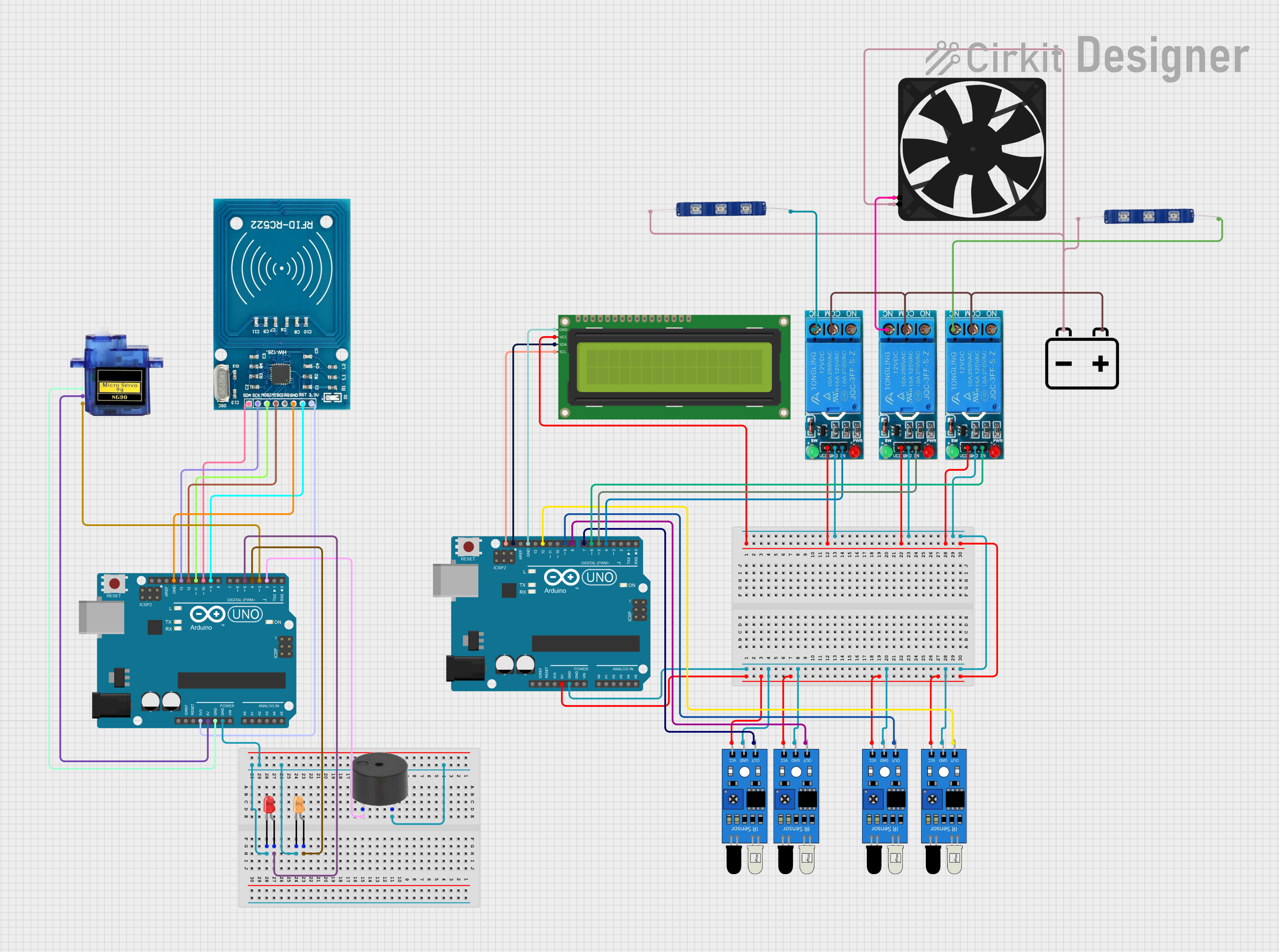
Circuit Documentation
Summary
This circuit is designed to manage a visitor counter system using multiple IR sensors, relays, an LCD display, and an Arduino UNO. The system also includes an RFID reader for access control and a servo motor for physical actuation. The circuit is powered by a 12V battery and includes various LEDs and a buzzer for visual and auditory feedback.
Component List
IR Sensor
- Description: Infrared sensor used for detecting objects.
- Pins: out, gnd, vcc
12V Single Channel Relay
- Description: Relay module used for switching high voltage devices.
- Pins: NC, COM, NO, IN, GND, VCC
16x2 I2C LCD
- Description: LCD display for showing information.
- Pins: GND, VCC, SDA, SCL
Arduino UNO
- Description: Microcontroller board used for controlling the circuit.
- Pins: UNUSED, IOREF, Reset, 3.3V, 5V, GND, Vin, A0, A1, A2, A3, A4, A5, SCL, SDA, AREF, D13, D12, D11, D10, D9, D8, D7, D6, D5, D4, D3, D2, D1, D0
12V Battery
- Description: Power source for the circuit.
- Pins: -, +
12V Blue LED
- Description: Blue LED for visual indication.
- Pins: GND, VCC
Fan
- Description: Fan for cooling or ventilation.
- Pins: GND, 5V
RFID-RC522
- Description: RFID reader for access control.
- Pins: VCC (3.3V), RST, GND, IRQ, MISO, MOSI, SCK, SDA
Micro Servo 9G
- Description: Servo motor for physical actuation.
- Pins: GND, +5V, PWM
LED: Two Pin (red)
- Description: Red LED for visual indication.
- Pins: cathode, anode
LED: Two Pin (orange)
- Description: Orange LED for visual indication.
- Pins: cathode, anode
Buzzer
- Description: Buzzer for auditory feedback.
- Pins: PIN, GND
Wiring Details
IR Sensor
- out: Connected to Arduino UNO D12, D9, D8, D7
- gnd: Connected to Arduino UNO GND
- vcc: Connected to Arduino UNO 5V
12V Single Channel Relay
- NC: Connected to 12V Blue LED VCC, Fan 5V
- COM: Connected to 12V Battery +
- NO: Not connected
- IN: Connected to Arduino UNO D4, D5, D6
- GND: Connected to Arduino UNO GND
- VCC: Connected to Arduino UNO 5V
16x2 I2C LCD
- GND: Connected to Arduino UNO GND
- VCC: Connected to Arduino UNO 5V
- SDA: Connected to Arduino UNO SDA
- SCL: Connected to Arduino UNO SCL
Arduino UNO
- 5V: Connected to IR Sensor vcc, 16x2 I2C LCD VCC, 12V Single Channel Relay VCC
- GND: Connected to IR Sensor gnd, 16x2 I2C LCD GND, 12V Single Channel Relay GND, Buzzer GND, LED (orange) cathode, LED (red) cathode, RFID-RC522 GND, Micro Servo 9G GND
- D2: Connected to Buzzer PIN
- D3: Connected to Micro Servo 9G PWM
- D4: Connected to 12V Single Channel Relay IN, LED (orange) anode
- D5: Connected to 12V Single Channel Relay IN, LED (red) anode
- D6: Connected to 12V Single Channel Relay IN
- D7: Connected to IR Sensor out
- D8: Connected to IR Sensor out
- D9: Connected to IR Sensor out, RFID-RC522 RST
- D10: Connected to RFID-RC522 SDA
- D11: Connected to RFID-RC522 MOSI
- D12: Connected to RFID-RC522 MISO
- D13: Connected to RFID-RC522 SCK
- SDA: Connected to 16x2 I2C LCD SDA
- SCL: Connected to 16x2 I2C LCD SCL
- 3.3V: Connected to RFID-RC522 VCC (3.3V)
12V Battery
- -: Connected to Fan GND, 12V Blue LED GND
- +: Connected to 12V Single Channel Relay COM
12V Blue LED
- GND: Connected to 12V Battery -
- VCC: Connected to 12V Single Channel Relay NC
Fan
- GND: Connected to 12V Battery -
- 5V: Connected to 12V Single Channel Relay NC
RFID-RC522
- VCC (3.3V): Connected to Arduino UNO 3.3V
- RST: Connected to Arduino UNO D9
- GND: Connected to Arduino UNO GND
- IRQ: Not connected
- MISO: Connected to Arduino UNO D12
- MOSI: Connected to Arduino UNO D11
- SCK: Connected to Arduino UNO D13
- SDA: Connected to Arduino UNO D10
Micro Servo 9G
- GND: Connected to Arduino UNO GND
- +5V: Connected to Arduino UNO 5V
- PWM: Connected to Arduino UNO D3
LED: Two Pin (red)
- cathode: Connected to Arduino UNO GND
- anode: Connected to Arduino UNO D5
LED: Two Pin (orange)
- cathode: Connected to Arduino UNO GND
- anode: Connected to Arduino UNO D4
Buzzer
- PIN: Connected to Arduino UNO D2
- GND: Connected to Arduino UNO GND
Documented Code
Arduino UNO (Visitor Counter System)
#include <LiquidCrystal_I2C.h>
#include <Servo.h>
Servo myservo;
LiquidCrystal_I2C lcd(0x27, 16,2);
#define sensorPin1 7
#define sensorPin2 8
#define sensorPin3 9
#define sensorPin4 12
#define relay1 4
#define relay2 5
#define relay3 6
#define SERVO_PIN 3
int sensorState1 = 0;
int sensorState2 = 0;
int sensorState3 = 0;
int sensorState4 = 0;
int count=0;
int count1=0;

void setup()
{
  myservo.attach(3);
  pinMode (sensorPin1, INPUT_PULLUP);
  pinMode (sensorPin2, INPUT_PULLUP);
  pinMode (sensorPin3, INPUT_PULLUP);
  pinMode (sensorPin4, INPUT_PULLUP);
  pinMode(relay1, OUTPUT);
  pinMode(relay2, OUTPUT);
  pinMode(relay3, OUTPUT);
  pinMode(SERVO_PIN, OUTPUT);
  digitalWrite(SERVO_PIN, HIGH);

  lcd.begin(16,2);
  lcd.backlight();
  lcd.setCursor(4,0);
  lcd.print("COUNTER");
   lcd.setCursor(0,1);
  lcd.print("No Visitors     ");
  delay(200);
}

void loop()
{
  sensorState1 = digitalRead(sensorPin1);
  sensorState2 = digitalRead(sensorPin2);
  sensorState3 = digitalRead(sensorPin3);
  sensorState4 = digitalRead(sensorPin4);

  if(sensorState1 == LOW){
    count++;
    delay(500);
  }

  if(sensorState2 == LOW){
    count--;
    delay(500);
  }
  if(sensorState3 == LOW){
    count1++;
    delay(500);
  }

  if(sensorState4 == LOW){
    count1--;
    delay(500);
  }

   if(count<=0)
  {
    digitalWrite(relay1, HIGH);
    myservo.write(-180);
    lcd.setCursor(0,1);
    lcd.print("No visitors    ");
  }
  else if (count>0 && count<100){
    digitalWrite(relay