
Dual Motor Control Circuit with LED Indicator and Adjustable Speed
View and Edit Project In Cirkit Designer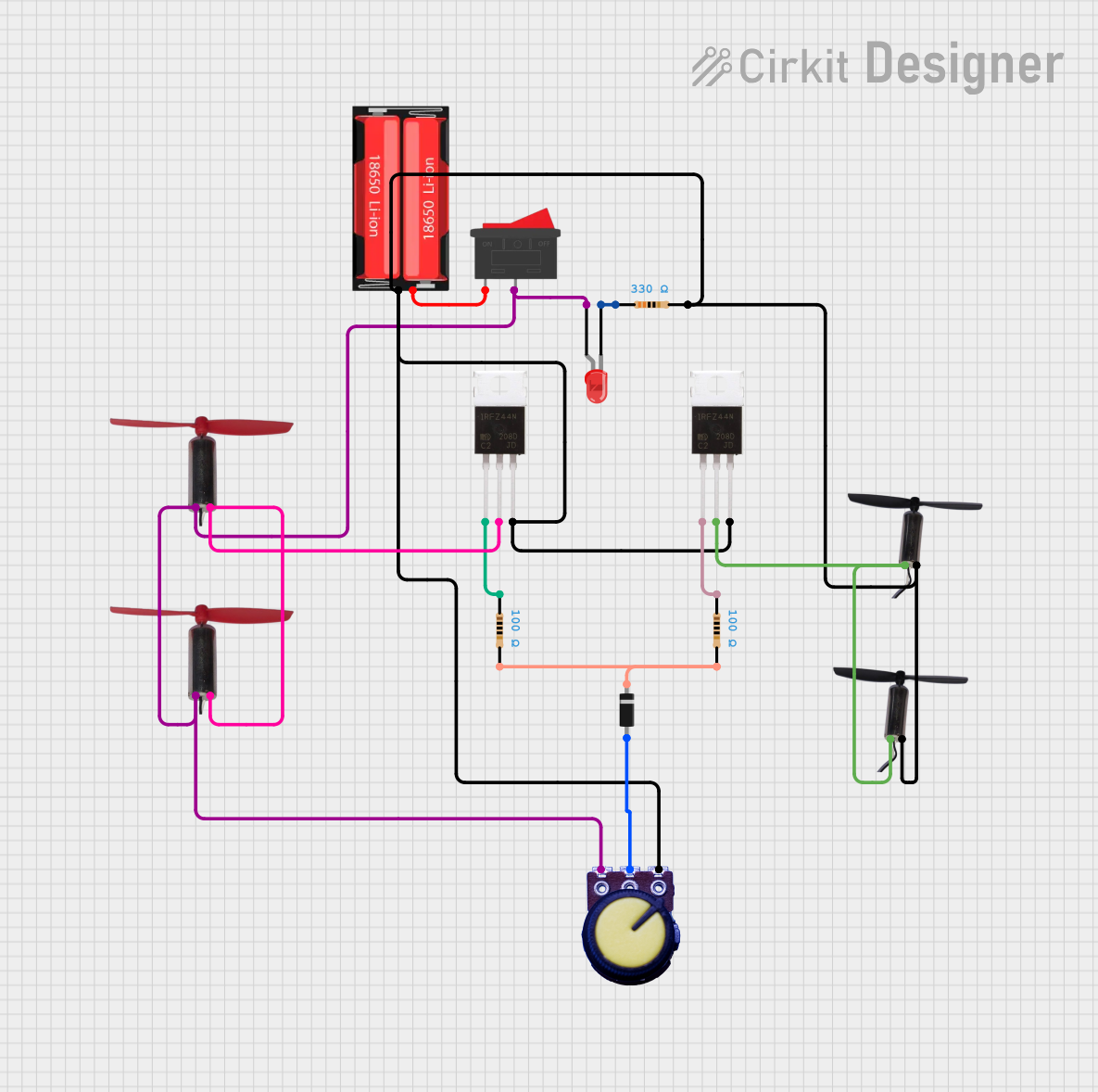
Circuit Documentation
Summary
The circuit in question appears to be a control circuit for driving coreless motors, both in clockwise and anti-clockwise directions, with a power supply from a single 18650 Li-Ion battery. It includes a switching mechanism for power control, a potentiometer for voltage adjustment, and IRFZ44N MOSFETs for controlling the motors. Additionally, there is an LED with a current-limiting resistor for indication purposes and a diode for protecting against reverse current.
Component List
18650 Li-Ion Battery
- Description: A rechargeable lithium-ion battery cell.
- Pins: Positive, Negative
IRFZ44N MOSFET
- Description: A power MOSFET used for switching and amplifying electronic signals.
- Pins: Gate, Drain, Source
Coreless Motor Clock
- Description: A small DC motor that rotates in the clockwise direction.
- Pins: +, -
Coreless Motor AntiClock
- Description: A small DC motor that rotates in the anti-clockwise direction.
- Pins: +, -
LED: Two Pin (red)
- Description: A red light-emitting diode used for indication.
- Pins: cathode, anode
Resistor (100 Ohms)
- Description: A resistor with a resistance of 100 Ohms.
- Pins: pin1, pin2
Resistor (330 Ohms)
- Description: A resistor with a resistance of 330 Ohms.
- Pins: pin1, pin2
Rocker Switch
- Description: A switch used to connect or disconnect the circuit.
- Pins: 1, 2
Diode
- Description: A semiconductor device that allows current to flow in one direction only.
- Pins: cathode, anode
Potentiometer
- Description: A three-terminal resistor with an adjustable center tap, used as an adjustable voltage divider.
- Pins: GND, Output, VCC
Wiring Details
18650 Li-Ion Battery
- Positive: Connected to Rocker Switch pin 1
- Negative: Common ground net connecting to Potentiometer GND, both Coreless Motor AntiClock motors -, both IRFZ44N Source pins, and Resistor (330 Ohms) pin2
IRFZ44N MOSFET (x2)
- Gate: One connected to Resistor (100 Ohms) pin1, the other to Resistor (100 Ohms) pin1
- Drain: One connected to both Coreless Motor AntiClock motors +, the other to both Coreless Motor Clock motors -
- Source: Both connected to the common ground net
Coreless Motor Clock (x2)
- +: Connected to Potentiometer VCC, Rocker Switch pin 2, and LED anode through Resistor (330 Ohms)
- -: Connected to IRFZ44N Drain
Coreless Motor AntiClock (x2)
- +: Connected to IRFZ44N Drain
- -: Connected to the common ground net
LED: Two Pin (red)
- anode: Connected to Potentiometer VCC through Resistor (330 Ohms)
- cathode: Connected to the common ground net through Resistor (330 Ohms)
Resistor (100 Ohms) (x2)
- pin1: Connected to IRFZ44N Gate
- pin2: Connected to the common ground net through Diode cathode
Resistor (330 Ohms)
- pin1: Connected to LED cathode
- pin2: Connected to the common ground net
Rocker Switch
- pin 1: Connected to 18650 Li-Ion Positive
- pin 2: Connected to Potentiometer VCC, Coreless Motor Clock motors +, and LED anode through Resistor (330 Ohms)
Diode
- anode: Connected to Potentiometer Output
- cathode: Connected to the common ground net through Resistor (100 Ohms) pin2
Potentiometer
- GND: Connected to the common ground net
- Output: Connected to Diode anode
- VCC: Connected to Rocker Switch pin 2, Coreless Motor Clock motors +, and LED anode through Resistor (330 Ohms)
Documented Code
There is no embedded code provided for any microcontrollers in this circuit. If there are any programmable components or future code additions, this section will be updated accordingly.