ESP32-Controlled Robotics Platform with Dual L298N Motor Drivers and Sensor Integration
Circuit Documentation
Summary
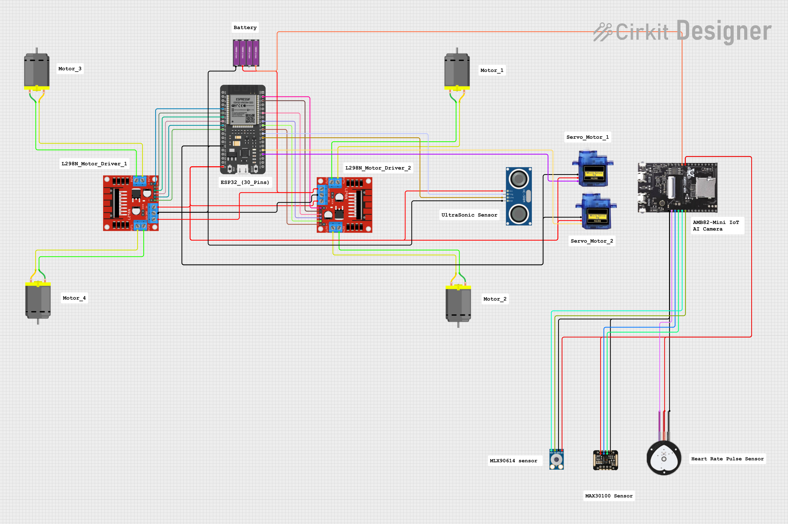
This circuit primarily consists of an ESP32 microcontroller, two L298N DC motor drivers, four DC motors, two sets of 18650 Li-ion batteries, an HC-SR04 ultrasonic sensor, an AMB82-Mini IoT AI Camera, a mlx90614 infrared temperature sensor, a MAX30100 pulse oximeter, a heart pulse sensor, and two micro servos. The ESP32 is used as the central processing unit, interfacing with the motor drivers, sensors, and servos to control the motors and gather data from the sensors. The motor drivers are responsible for controlling the speed and direction of the DC motors. The batteries provide power to the system, while the sensors and camera are used for various detection and measurement tasks.
Component List
ESP32 - 38 pins
- Microcontroller with WiFi and Bluetooth capabilities.
- 38 pins including GPIOs, power, and communication interfaces.
L298N DC Motor Driver (x2)
- Module for controlling the direction and speed of DC motors.
- Multiple input and output pins for motor and power connections.
DC Motor (x4)
- Electric motor that converts electrical energy into mechanical motion.
18650 Li-ion Battery x 2 (x2)
- Rechargeable battery pack providing power to the circuit.
HC-SR04 Ultrasonic Sensor
- Sensor for measuring distance using ultrasonic waves.
AMB82-Mini IoT AI Camera
- Compact camera module with AI capabilities for image processing.
mlx90614
- Infrared temperature sensor for non-contact temperature measurements.
MAX30100
- Integrated pulse oximetry and heart-rate sensor module.
Heart Pulse Sensor
- Sensor for detecting heartbeats.
Micro servo 9G (x2)
- Small servo motor for precise control of mechanical movement.
Comments
- Additional notes or annotations about the circuit (not a physical component).
Wiring Details
ESP32 - 38 pins
- G34: Connected to L298N DC motor driver ENB
- G35: Connected to L298N DC motor driver IN4
- G32: Connected to L298N DC motor driver IN3
- G33: Connected to L298N DC motor driver IN2
- G25: Connected to L298N DC motor driver IN1
- G26: Connected to L298N DC motor driver ENA
- GND: Common ground with various components
- 5V: Power supply to HC-SR04 Ultrasonic Sensor and Micro servos
- G23: Connected to L298N DC motor driver ENA
- G22: Connected to L298N DC motor driver IN1
- G21: Connected to L298N DC motor driver IN2
- G19: Connected to L298N DC motor driver IN3
- G18: Connected to L298N DC motor driver IN4
- G5: Connected to L298N DC motor driver ENB
- G17: Connected to HC-SR04 Ultrasonic Sensor TRIG
- G16: Connected to HC-SR04 Ultrasonic Sensor ECHO
- G2: Connected to Micro servo 9G PWM
- G15: Connected to Micro servo 9G PWM
L298N DC Motor Driver (x2)
- OUT1, OUT2, OUT3, OUT4: Connected to DC Motors
- 12V: Power input from 18650 Li-ion Battery x 2
- GND: Common ground with various components
- 5V: Power output to Micro servos
- ENA, ENB, IN1, IN2, IN3, IN4: Control inputs from ESP32
DC Motor (x4)
- pin 1, pin 2: Connected to L298N DC motor driver OUT1, OUT2, OUT3, OUT4 respectively
18650 Li-ion Battery x 2 (x2)
- +: Power supply to L298N DC motor drivers and AMB82-Mini IoT AI Camera
- -: Common ground with various components
HC-SR04 Ultrasonic Sensor
- VCC: Power supply from ESP32
- TRIG: Trigger input from ESP32
- ECHO: Echo output to ESP32
- GND: Common ground with various components
AMB82-Mini IoT AI Camera
- V_USB, VDD33: Power supply from 18650 Li-ion Battery x 2
- GND: Common ground with various components
- PA3: Connected to Heart Pulse Sensor SIGNAL
- PA2, PD14: Connected to MAX30100 SDA, SCL respectively
- PD15, PD16: Connected to mlx90614 SDA, SCL respectively
mlx90614
- VIN: Power supply from 18650 Li-ion Battery x 2
- SDA, SCL: Communication with AMB82-Mini IoT AI Camera
- GND: Common ground with various components
MAX30100
- VIN: Power supply from 18650 Li-ion Battery x 2
- SDA, SCL: Communication with AMB82-Mini IoT AI Camera
- GND: Common ground with various components
Heart Pulse Sensor
- VCC: Power supply from 18650 Li-ion Battery x 2
- SIGNAL: Output to AMB82-Mini IoT AI Camera
- GND: Common ground with various components
Micro servo 9G (x2)
- +5V: Power supply from L298N DC motor driver
- PWM: Control input from ESP32
- GND: Common ground with various components
Documented Code
No code has been provided for the microcontrollers in the circuit. The documentation of the code would typically include descriptions of the functions, algorithms, and communication protocols used to interface with the sensors, motor drivers, and other components. It would also detail the logic for motor control, sensor data processing, and any communication with external devices or services.