Cirkit Designer
Your all-in-one circuit design IDE
Home /
Project Documentation
Arduino UNO-Based Automated Watering System with Ultrasonic Sensing and Servo Control
Circuit Documentation
Summary
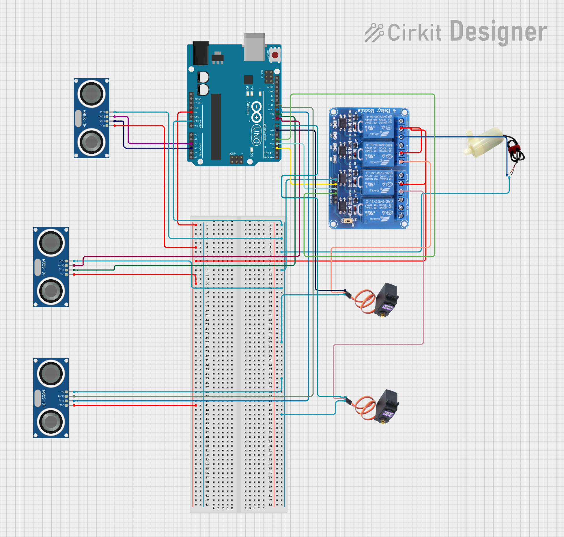
This circuit is designed to interface an Arduino UNO with multiple sensors and actuators. It includes HC-SR04 ultrasonic sensors for distance measurement, a 4-channel relay module to control external devices such as a mini water pump, and MG996R servos for motion control. The Arduino UNO serves as the central processing unit, reading sensor data and controlling the actuators based on programmed logic.
Component List
Arduino UNO
- Microcontroller board based on the ATmega328P
- It has 14 digital input/output pins, 6 analog inputs, a 16 MHz quartz crystal, a USB connection, a power jack, an ICSP header, and a reset button.
HC-SR04 Ultrasonic Sensor
- Ultrasonic distance sensor
- Provides 2cm to 400cm non-contact measurement functionality with a ranging accuracy that can reach up to 3mm.
Relay 4 Channel 5V
- 4-channel relay module
- Allows for controlling high power/high voltage devices safely.
5V Mini Water Pump
- Submersible water pump
- Operates on 5V and can be used for small-scale projects.
MG996R Servo
- High-torque digital servo motor
- Suitable for applications where standard servos are not strong enough.
Wiring Details
Arduino UNO
- 5V connected to:
- VCC of all HC-SR04 Ultrasonic Sensors
- COM pins of Relay 4 Channel 5V
- GND connected to:
- GND of all HC-SR04 Ultrasonic Sensors
- GND of Relay 4 Channel 5V
- GND of MG996R Servos
- Negative pin of 5V Mini Water Pump
- A2 connected to ECHO of HC-SR04 Ultrasonic Sensor
- A3 connected to TRIG of HC-SR04 Ultrasonic Sensor
- D11 connected to ECHO of another HC-SR04 Ultrasonic Sensor
- D10 connected to TRIG of another HC-SR04 Ultrasonic Sensor
- D9 connected to TRIG of another HC-SR04 Ultrasonic Sensor
- D8 connected to ECHO of another HC-SR04 Ultrasonic Sensor
- D7 connected to SIG of MG996R Servo
- D6 connected to SIG of another MG996R Servo
- D4 connected to IN3 of Relay 4 Channel 5V
- D3 connected to IN2 of Relay 4 Channel 5V
- D2 connected to IN1 of Relay 4 Channel 5V
HC-SR04 Ultrasonic Sensor
- VCC connected to 5V of Arduino UNO
- GND connected to GND of Arduino UNO
- ECHO connected to A2, D11, or D8 of Arduino UNO (depending on the sensor)
- TRIG connected to A3, D10, or D9 of Arduino UNO (depending on the sensor)
Relay 4 Channel 5V
- GND connected to GND of Arduino UNO
- IN1, IN2, IN3 connected to D2, D3, D4 of Arduino UNO respectively
- NO1 connected to the positive pin of 5V Mini Water Pump
- COM1, COM2, COM3 connected to 5V of Arduino UNO
- NO2, NO3 connected to VCC of MG996R Servos
5V Mini Water Pump
- Positive pin connected to NO1 of Relay 4 Channel 5V
- Negative pin connected to GND of Arduino UNO
MG996R Servo
- VCC connected to NO2 or NO3 of Relay 4 Channel 5V (depending on the servo)
- GND connected to GND of Arduino UNO
- SIG connected to D7 or D6 of Arduino UNO (depending on the servo)
Documented Code
Arduino UNO Code (sketch.ino)
void setup() {
  // put your setup code here, to run once:

}

void loop() {
  // put your main code here, to run repeatedly:

}
Note: The provided code is a template and does not contain any functional logic. It needs to be populated with the setup and loop functions to control the sensors and actuators based on the specific requirements of the circuit.