
ESP32-Based Smart Weather Station with BME280, BH1750, and OLED Display
View and Edit Project In Cirkit Designer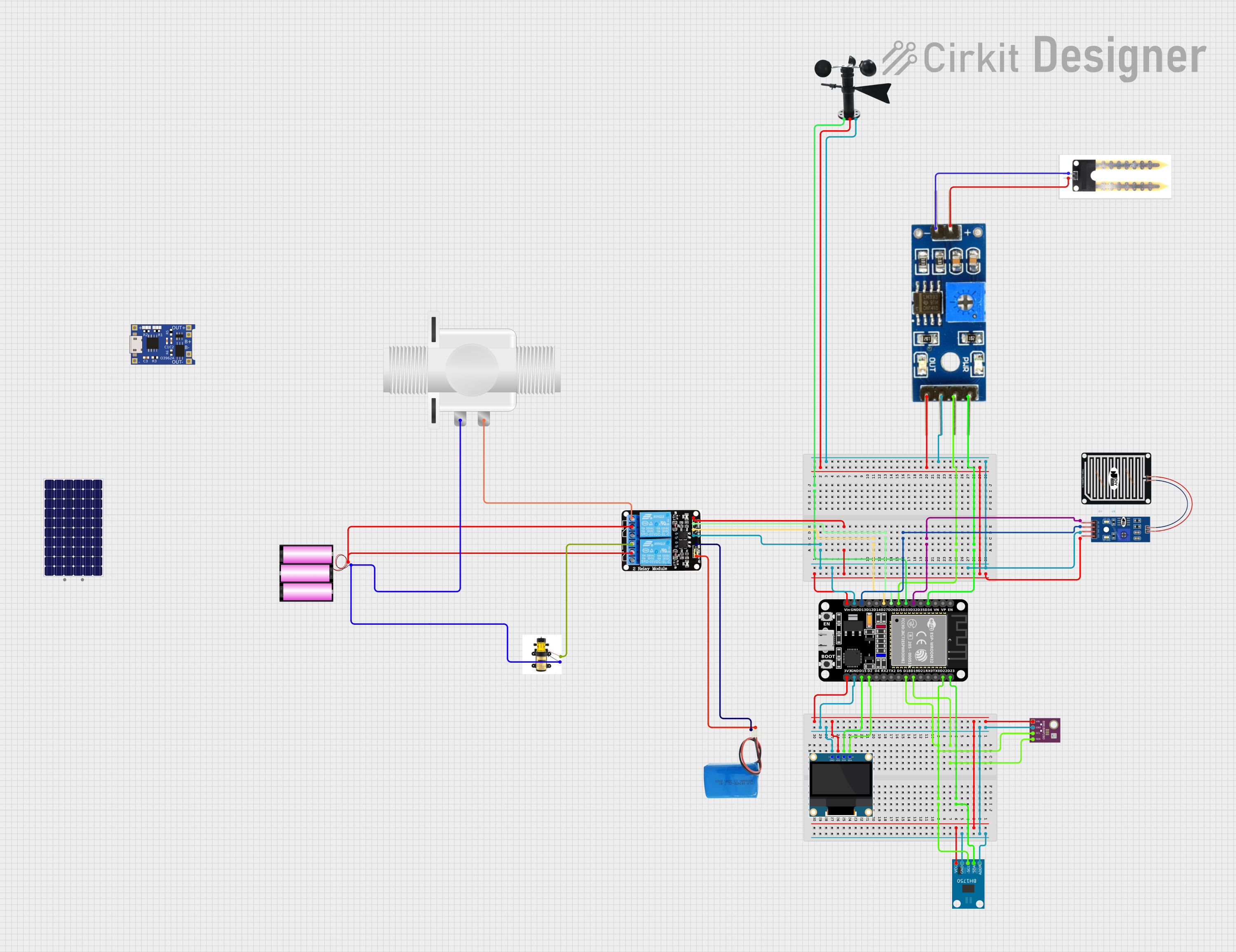
Smart Weather Station Circuit Documentation
Summary
This document provides a detailed overview of a smart weather station circuit. The circuit integrates various sensors and an OLED display to measure and display environmental parameters such as temperature, humidity, pressure, and light intensity. The core of the circuit is an ESP32 microcontroller, which interfaces with a BME280 sensor, a BH1750 sensor, a wind vane, a rain sensor, a soil moisture sensor, and a 0.96" OLED display. Additionally, the circuit includes a relay module to control a pump and a solenoid valve.
Component List
BME/BMP280
- Description: Sensor for measuring temperature, humidity, and pressure.
- Pins: GND, SCL, SDA, VIN
Wind Vane
- Description: Sensor for measuring wind direction.
- Pins: A0, VCC, GND
0.96" OLED
- Description: Display for showing sensor readings.
- Pins: GND, VDD, SCK, SDA
BH1750
- Description: Sensor for measuring light intensity.
- Pins: VCC, GND, SCL, SDA, ADDR
ESP32 (30 pin)
- Description: Microcontroller for processing sensor data and controlling the display.
- Pins: EN, VP, VN, D34, D35, D32, D33, D25, D26, D27, D14, D12, D13, GND, Vin, D23, D22, TX0, RX0, D21, D19, D18, D5, TX2, RX2, D4, D2, D15, 3V3
Soil Moisture Sensor
- Description: Sensor for measuring soil moisture.
- Pins: positive, negative
5v 2-Relay JD-VCC
- Description: Relay module for controlling external devices like a pump and solenoid valve.
- Pins: JD-VCC, VCC, GND, IN1, IN2, NO, COM, NC
Pump
- Description: Device for pumping water.
- Pins: +, -
Plastic Solenoid Valve
- Description: Valve for controlling water flow.
- Pins: pin1, pin2
Battery 12v
- Description: Power source for the circuit.
- Pins: +, -
5v Battery
- Description: Power source for the relay module.
- Pins: positive, negative
Rain Sensor
- Description: Sensor for detecting rain.
- Pins: AO, DO, GRD, VCC
TP4056
- Description: Battery charging module.
- Pins: OUT-, B-, B+, OUT+, IN-, IN+
Solar Panel
- Description: Power source for charging the battery.
- Pins: +, -
Soil Moisture Module
- Description: Module for interfacing with the soil moisture sensor.
- Pins: positive, negative, Analog, Digital, Ground, VCC
Wiring Details
BME/BMP280
- SDA: Connected to ESP32 D19
- SCL: Connected to ESP32 D18
- VIN: Connected to ESP32 3V3 and OLED VDD and BH1750 VCC
- GND: Connected to ESP32 GND and OLED GND and BH1750 GND
Wind Vane
- A0: Connected to ESP32 D33
- VCC: Connected to ESP32 Vin and Relay VCC and Rain Sensor VCC and Soil Moisture Module VCC
- GND: Connected to ESP32 GND and Relay GND and Rain Sensor GRD and Soil Moisture Module Ground
0.96" OLED
- SDA: Connected to ESP32 D2
- SCK: Connected to ESP32 D15
- VDD: Connected to ESP32 3V3 and BME/BMP280 VIN and BH1750 VCC
- GND: Connected to ESP32 GND and BME/BMP280 GND and BH1750 GND
BH1750
- SDA: Connected to ESP32 D23
- SCL: Connected to ESP32 D22
- VCC: Connected to ESP32 3V3 and OLED VDD and BME/BMP280 VIN
- GND: Connected to ESP32 GND and OLED GND and BME/BMP280 GND
- ADDR: Connected to ESP32 GND
ESP32 (30 pin)
- D19: Connected to BME/BMP280 SDA
- D18: Connected to BME/BMP280 SCL
- D23: Connected to BH1750 SDA
- D22: Connected to BH1750 SCL
- D2: Connected to OLED SDA
- D15: Connected to OLED SCK
- 3V3: Connected to OLED VDD and BME/BMP280 VIN and BH1750 VCC
- GND: Connected to OLED GND and BME/BMP280 GND and BH1750 GND
- D33: Connected to Wind Vane A0
- Vin: Connected to Relay VCC and Rain Sensor VCC and Wind Vane VCC and Soil Moisture Module VCC
- D27: Connected to Relay IN1
- D26: Connected to Relay IN2
- D13: Connected to Rain Sensor DO
- D32: Connected to Rain Sensor AO
- D25: Connected to Soil Moisture Module Digital
- D34: Connected to Soil Moisture Module Analog
Soil Moisture Sensor
- positive: Connected to Soil Moisture Module positive
- negative: Connected to Soil Moisture Module negative
5v 2-Relay JD-VCC
- GND: Connected to ESP32 GND and 5v Battery negative
- VCC: Connected to ESP32 Vin and Rain Sensor VCC and Wind Vane VCC and Soil Moisture Module VCC
- IN1: Connected to ESP32 D27
- IN2: Connected to ESP32 D26
- NO: Connected to Plastic Solenoid Valve pin2 and Pump +
- COM: Connected to Battery 12v +
- JD-VCC: Connected to 5v Battery positive
Pump
- +: Connected to Relay NO
- -: Connected to Battery 12v -
Plastic Solenoid Valve
- pin1: Connected to Battery 12v -
- pin2: Connected to Relay NO
Battery 12v
- +: Connected to Relay COM
- -: Connected to Pump - and Plastic Solenoid Valve pin1
5v Battery
- positive: Connected to Relay JD-VCC
- negative: Connected to Relay GND
Rain Sensor
- AO: Connected to ESP32 D32
- DO: Connected to ESP32 D13
- GRD: Connected to ESP32 GND and Relay GND and Wind Vane GND and Soil Moisture Module Ground
- VCC: Connected to ESP32 Vin and Relay VCC and Wind Vane VCC and Soil Moisture Module VCC
TP4056
- OUT-: Not connected
- B-: Not connected
- B+: Not connected
- OUT+: Not connected
- IN-: Not connected
- IN+: Not connected
Solar Panel
- +: Not connected
- -: Not connected
Soil Moisture Module
- positive: Connected to Soil Moisture Sensor positive
- negative: Connected to Soil Moisture Sensor negative
- Analog: Connected to ESP32 D34
- Digital: Connected to ESP32 D25
- Ground: Connected to ESP32 GND and Relay GND and Rain Sensor GRD and Wind Vane GND
- VCC: Connected to ESP32 Vin and Relay VCC and Rain Sensor VCC and Wind Vane VCC
Code Documentation
/*
 * Smart Weather Station
 * This Arduino sketch interfaces with a BME280 sensor, BH1750 sensor, and an
 * OLED display to create a smart weather station. The BME280 sensor measures
 * temperature, humidity, and pressure. The BH1750 sensor measures light
 * intensity. The OLED display shows the sensor readings.
 */

#include <Wire.h>
#include <Adafruit_Sensor.h>
#include <Adafruit_BME280.h>
#include <Adafruit_GFX