Cirkit Designer
Your all-in-one circuit design IDE
Home /
Project Documentation
Arduino UNO-Based Smart Control System with RFID and I2C LCD Display
Circuit Documentation
Summary
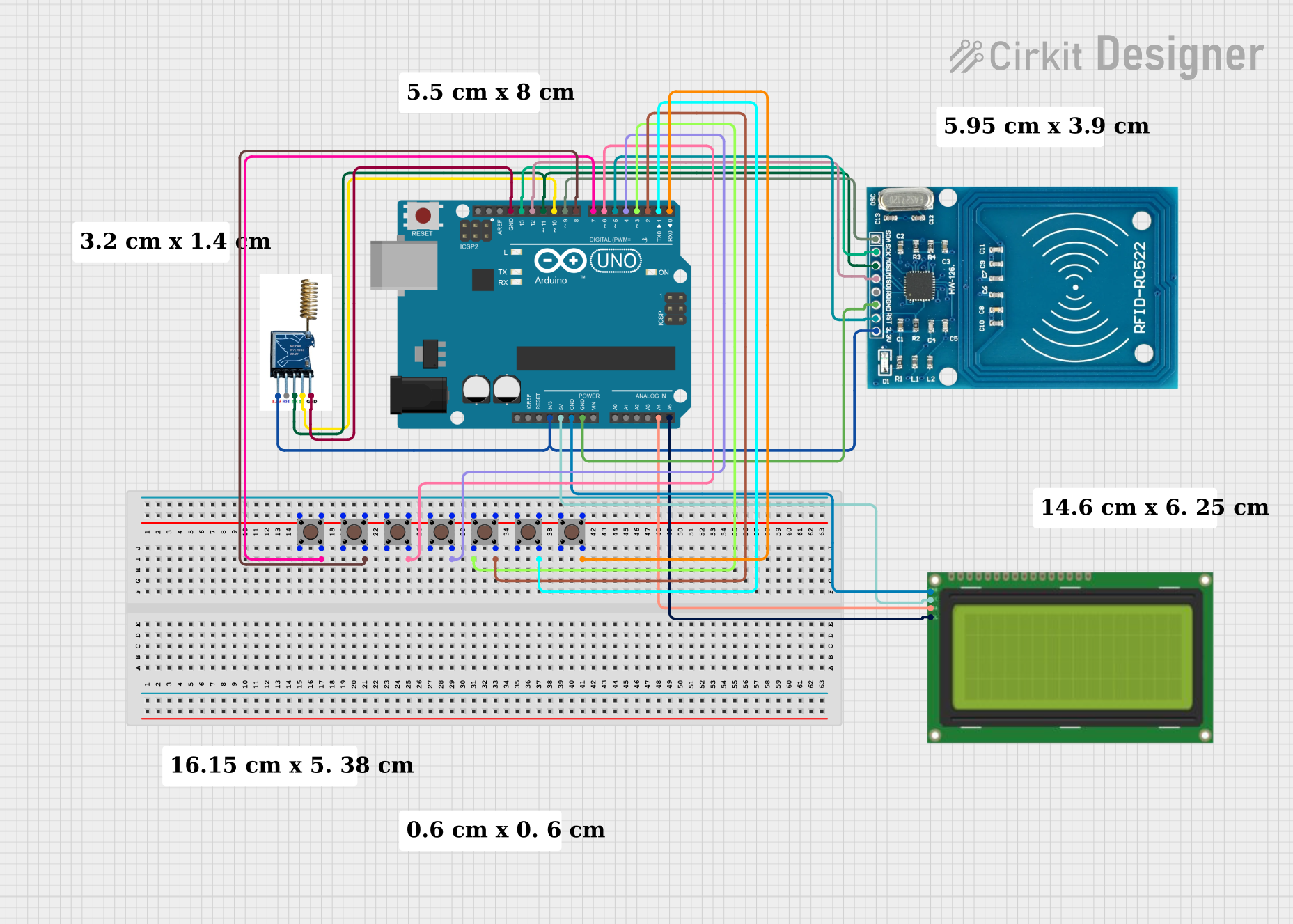
This document provides a detailed overview of a circuit that includes an Arduino UNO microcontroller, an RYLR998 LoRa module, an LCD 20x4 I2C display, an RFID-RC522 module, and multiple pushbuttons. The circuit is designed to interface these components with the Arduino UNO, allowing for various input and output operations.
Component List
Arduino UNO
- Description: A microcontroller board based on the ATmega328P.
- Pins: UNUSED, IOREF, Reset, 3.3V, 5V, GND, Vin, A0, A1, A2, A3, A4, A5, SCL, SDA, AREF, D13, D12, D11, D10, D9, D8, D7, D6, D5, D4, D3, D2, D1, D0
RYLR998
- Description: A LoRa module for long-range communication.
- Pins: 3.3V, RST, RX, TX, GND
LCD 20x4 I2C
- Description: A 20x4 character LCD display with I2C interface.
- Pins: GND, 5V, SCA, SCL
RFID-RC522
- Description: An RFID module for reading and writing RFID tags.
- Pins: VCC (3.3V), RST, GND, IRQ, MISO, MOSI, SCK, SDA
Pushbutton
- Description: A simple pushbutton switch.
- Pins: Pin 3 (out), Pin 4 (out), Pin 1 (in), Pin 2 (in)
Wiring Details
Arduino UNO
- 3.3V: Connected to 3.3V pin of RYLR998 and VCC (3.3V) pin of RFID-RC522.
- 5V: Connected to 5V pin of LCD 20x4 I2C.
- GND: Connected to GND pin of LCD 20x4 I2C, GND pin of RFID-RC522, and GND pin of RYLR998.
- A4: Connected to SCA pin of LCD 20x4 I2C.
- A5: Connected to SCL pin of LCD 20x4 I2C.
- D0: Connected to Pin 4 (out) of a pushbutton.
- D1: Connected to Pin 4 (out) of a pushbutton.
- D2: Connected to Pin 4 (out) of a pushbutton.
- D3: Connected to Pin 2 (in) of a pushbutton.
- D4: Connected to Pin 4 (out) of a pushbutton.
- D5: Connected to RST pin of RFID-RC522.
- D6: Connected to Pin 4 (out) of a pushbutton.
- D7: Connected to Pin 4 (out) of a pushbutton.
- D8: Connected to Pin 4 (out) of a pushbutton.
- D9: Connected to SDA pin of RFID-RC522.
- D10: Connected to TX pin of RYLR998.
- D11: Connected to RX pin of RYLR998 and MOSI pin of RFID-RC522.
- D12: Connected to MISO pin of RFID-RC522.
- D13: Connected to SCK pin of RFID-RC522.
RYLR998
- 3.3V: Connected to 3.3V pin of Arduino UNO.
- GND: Connected to GND pin of Arduino UNO.
- RX: Connected to D11 pin of Arduino UNO.
- TX: Connected to D10 pin of Arduino UNO.
LCD 20x4 I2C
- 5V: Connected to 5V pin of Arduino UNO.
- GND: Connected to GND pin of Arduino UNO.
- SCA: Connected to A4 pin of Arduino UNO.
- SCL: Connected to A5 pin of Arduino UNO.
RFID-RC522
- VCC (3.3V): Connected to 3.3V pin of Arduino UNO.
- GND: Connected to GND pin of Arduino UNO.
- RST: Connected to D5 pin of Arduino UNO.
- MISO: Connected to D12 pin of Arduino UNO.
- MOSI: Connected to D11 pin of Arduino UNO.
- SCK: Connected to D13 pin of Arduino UNO.
- SDA: Connected to D9 pin of Arduino UNO.
Pushbuttons
- Pushbutton 1:
- Pin 4 (out): Connected to D7 pin of Arduino UNO.
- Pin 3 (out): Connected to Pin 1 (in) of the same pushbutton.
- Pushbutton 2:
- Pin 4 (out): Connected to D8 pin of Arduino UNO.
- Pin 3 (out): Connected to Pin 1 (in) of the same pushbutton.
- Pushbutton 3:
- Pin 4 (out): Connected to D6 pin of Arduino UNO.
- Pin 3 (out): Connected to Pin 1 (in) of the same pushbutton.
- Pushbutton 4:
- Pin 4 (out): Connected to D4 pin of Arduino UNO.
- Pin 3 (out): Connected to Pin 1 (in) of the same pushbutton.
- Pushbutton 5:
- Pin 2 (in): Connected to D3 pin of Arduino UNO.
- Pin 4 (out): Connected to D2 pin of Arduino UNO.
- Pin 3 (out): Connected to Pin 1 (in) of the same pushbutton.
- Pushbutton 6:
- Pin 4 (out): Connected to D1 pin of Arduino UNO.
- Pin 3 (out): Connected to Pin 1 (in) of the same pushbutton.
- Pushbutton 7:
- Pin 4 (out): Connected to D0 pin of Arduino UNO.
- Pin 3 (out): Connected to Pin 1 (in) of the same pushbutton.
Documented Code
Arduino UNO Code (sketch.ino)
void setup() {
  // put your setup code here, to run once:

}

void loop() {
  // put your main code here, to run repeatedly:

}
This concludes the documentation for the circuit. Each component and its connections have been detailed, and the code for the Arduino UNO has been provided.