
Arduino UNO Controlled Robotic Arm with Multiple Servos and Ultrasonic Sensor
View and Edit Project In Cirkit Designer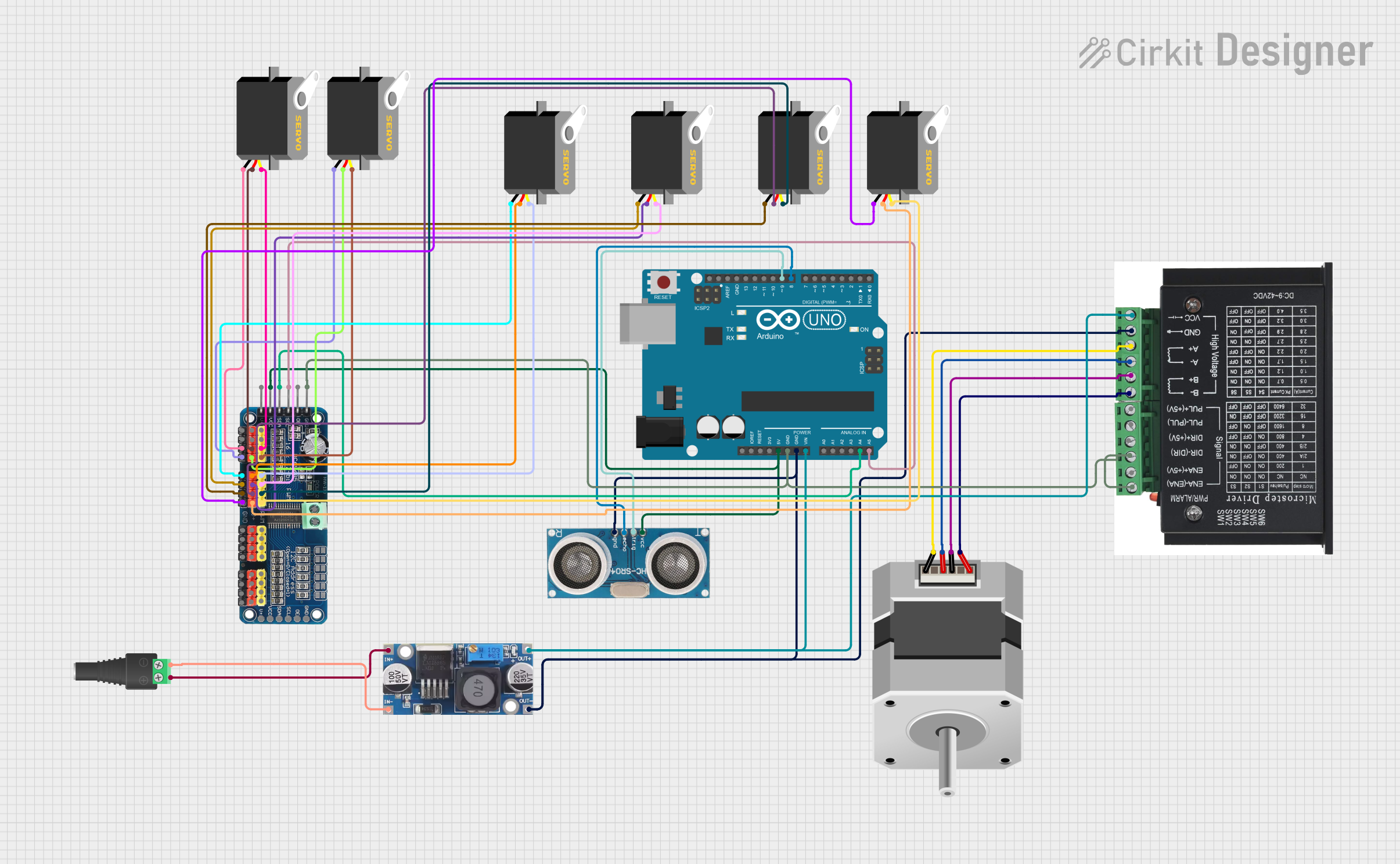
Circuit Documentation
Summary
This circuit involves an Arduino UNO microcontroller interfacing with multiple servos, a stepper motor, an ultrasonic sensor, a 16-channel PWM servo driver, a stepper driver, and a step-down buck converter. The circuit is designed to control the servos and stepper motor while receiving distance measurements from the ultrasonic sensor.
Component List
Arduino UNO
- Description: A microcontroller board based on the ATmega328P.
- Pins: UNUSED, IOREF, Reset, 3.3V, 5V, GND, Vin, A0, A1, A2, A3, A4, A5, SCL, SDA, AREF, D13, D12, D11, D10, D9, D8, D7, D6, D5, D4, D3, D2, D1, D0
Servo
- Description: A standard servo motor.
- Pins: gnd, vcc, pulse
16-Channel PWM Servo Driver
- Description: A driver board to control up to 16 servos using PWM signals.
- Pins: V+, VCC, SDA, SCL, OE, GND, Vin+, Vin-, PWM1, PWM2, PWM3, PWM4, PWM5, PWM6, PWM7, PWM8, PWM9, PWM10, PWM11, PWM12, PWM13, PWM14, PWM15, PWM16
Stepper Driver
- Description: A driver for controlling a bipolar stepper motor.
- Pins: ENA -, ENA +, DIR -, DIR+, PUL -, PUL +, B-, B+, A-, A+, GND, VCC
Stepper Motor (Bipolar)
- Description: A bipolar stepper motor.
- Pins: D, B, C, A
2.1mm Barrel Jack with Terminal Block
- Description: A power input jack with terminal block.
- Pins: POS, NEG
Ultrasonic Sensor
- Description: A sensor for measuring distance using ultrasonic waves.
- Pins: +VCC, Trigger, Echo, GND
Step Down Buck Converter
- Description: A DC-DC converter to step down voltage.
- Pins: IN +, IN - GND, OUT +, OUT - GND
Wiring Details
Arduino UNO
- 5V: Connected to +VCC of Ultrasonic Sensor and VCC of 16-Channel PWM Servo Driver
- GND: Connected to GND of Ultrasonic Sensor, GND of Stepper Driver, and OUT - GND of Step Down Buck Converter
- Vin: Connected to VCC of Stepper Driver and OUT + of Step Down Buck Converter
- A4: Connected to SDA of 16-Channel PWM Servo Driver
- A5: Connected to SCL of 16-Channel PWM Servo Driver
- D9: Connected to Trigger of Ultrasonic Sensor
- D8: Connected to Echo of Ultrasonic Sensor
Servo (6 instances)
- gnd: Connected to GND of 16-Channel PWM Servo Driver
- vcc: Connected to V+ of 16-Channel PWM Servo Driver
- pulse: Connected to PWM4, PWM5, PWM6, PWM7, PWM8, PWM3 of 16-Channel PWM Servo Driver
16-Channel PWM Servo Driver
- VCC: Connected to 5V of Arduino UNO
- GND: Connected to GND of Arduino UNO, GND of Stepper Driver, and OUT - GND of Step Down Buck Converter
- SDA: Connected to A4 of Arduino UNO
- SCL: Connected to A5 of Arduino UNO
- V+: Connected to vcc of all Servo instances
- PWM4: Connected to pulse of Servo
- PWM5: Connected to pulse of Servo
- PWM6: Connected to pulse of Servo
- PWM7: Connected to pulse of Servo
- PWM8: Connected to pulse of Servo
- PWM3: Connected to pulse of Servo
Stepper Driver
- ENA -: Connected to GND of Arduino UNO
- DIR -: Connected to GND of Arduino UNO
- GND: Connected to GND of Arduino UNO and OUT - GND of Step Down Buck Converter
- VCC: Connected to Vin of Arduino UNO and OUT + of Step Down Buck Converter
- B-: Connected to A of Stepper Motor
- B+: Connected to C of Stepper Motor
- A-: Connected to B of Stepper Motor
- A+: Connected to D of Stepper Motor
Stepper Motor (Bipolar)
- A: Connected to B- of Stepper Driver
- C: Connected to B+ of Stepper Driver
- B: Connected to A- of Stepper Driver
- D: Connected to A+ of Stepper Driver
2.1mm Barrel Jack with Terminal Block
- POS: Connected to IN + of Step Down Buck Converter
- NEG: Connected to IN - GND of Step Down Buck Converter
Ultrasonic Sensor
- +VCC: Connected to 5V of Arduino UNO
- GND: Connected to GND of Arduino UNO
- Trigger: Connected to D9 of Arduino UNO
- Echo: Connected to D8 of Arduino UNO
Step Down Buck Converter
- IN +: Connected to POS of 2.1mm Barrel Jack with Terminal Block
- IN - GND: Connected to NEG of 2.1mm Barrel Jack with Terminal Block
- OUT +: Connected to VCC of Stepper Driver and Vin of Arduino UNO
- OUT - GND: Connected to GND of Arduino UNO and GND of Stepper Driver
Documented Code
Arduino UNO Code (sketch.ino)
void setup() {
  // put your setup code here, to run once:

}

void loop() {
  // put your main code here, to run repeatedly:

}
Additional Documentation (documentation.txt)
This documentation provides a comprehensive overview of the circuit, including a summary, detailed component list, wiring details, and the code used in the Arduino UNO microcontroller.