
STM32 Nucleo F303RE Based Ultrasonic Distance Measurement System
View and Edit Project In Cirkit Designer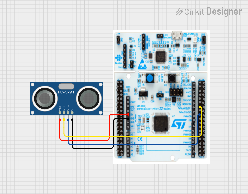
Circuit Documentation
Summary of the Circuit
This circuit integrates an STM32 Nucleo F303RE microcontroller board with an HC-SR04 Ultrasonic Sensor. The purpose of this circuit is to measure distances using the ultrasonic sensor, which sends out a pulse and receives an echo. The time taken for the echo to be detected is used to calculate the distance to an object. The STM32 Nucleo F303RE is responsible for triggering the ultrasonic pulse and measuring the time until the echo is received.
Component List
STM32 Nucleo F303RE
- Description: A microcontroller board based on the STM32F303RE MCU, which is a high-performance ARM Cortex-M4 32-bit microcontroller with DSP and FPU instructions.
- Pins: The board includes various digital and analog I/O pins, power supply pins, and ground.
- Purpose: Acts as the central processing unit of the circuit, controlling the ultrasonic sensor and processing the distance measurements.
HC-SR04 Ultrasonic Sensor
- Description: An ultrasonic ranging module that provides 2cm to 400cm non-contact measurement functionality with a ranging accuracy that can reach up to 3mm.
- Pins: VCC, TRIG, ECHO, GND.
- Purpose: To emit ultrasonic waves and detect the echo to measure the distance to an object.
Wiring Details
STM32 Nucleo F303RE
- VCC: Connected to +5V power supply.
- GND: Connected to the ground.
- PA6: Connected to the TRIG pin of the HC-SR04 Ultrasonic Sensor.
- PB6: Connected to the ECHO pin of the HC-SR04 Ultrasonic Sensor.
HC-SR04 Ultrasonic Sensor
- VCC: Connected to the +5V pin of the STM32 Nucleo F303RE.
- TRIG: Connected to pin PA6 on the STM32 Nucleo F303RE.
- ECHO: Connected to pin PB6 on the STM32 Nucleo F303RE.
- GND: Connected to the ground pin on the STM32 Nucleo F303RE.
Documented Code
No code has been provided for the microcontroller. To operate this circuit, embedded code is required to initialize the microcontroller's I/O pins, generate the ultrasonic pulses, and measure the time interval of the received echo. The code would typically involve setting up the microcontroller's timers, configuring the I/O pins for the TRIG and ECHO signals, and implementing an interrupt service routine to measure the time interval accurately.