
Circuit Documentation
Summary of the Circuit
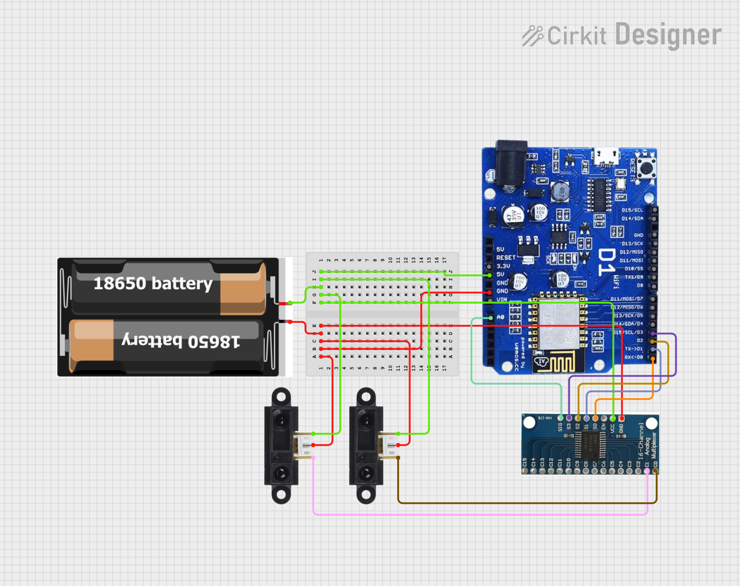
This circuit integrates a pair of Sharp IR Sensors with a WeMOS ESP8266 microcontroller and a 16-channel analog multiplexer. The circuit is powered by a 2x 18650 battery pack. The purpose of the circuit is to read analog signals from the IR sensors and process them using the ESP8266, which can then perform further actions based on the sensor readings. The analog multiplexer is used to expand the number of analog inputs that can be read by the single analog pin available on the ESP8266.
Component List
Sharp IR Sensor
- Description: An infrared distance sensor that outputs an analog signal corresponding to the distance of an object from the sensor.
- Pins: VCC, GND, Pin
2x 18650 Battery Pack
- Description: A power source for the circuit, consisting of two 18650 lithium-ion batteries.
- Pins: VCC, GND
WeMOS ESP8266
- Description: A microcontroller with WiFi capabilities, used for processing sensor data and potentially sending data over a network.
- Pins: A0, VIN, GND, 5V, 3.3V, D0-D8, D10-D15, 19
16 Channel Analog Multiplexer
- Description: A device that allows multiple analog signals to be routed to a single output pin.
- Pins: GND, VCC, EN, S0-S3, SIG, C0-C15
Wiring Details
Sharp IR Sensor
- VCC: Connected to the positive terminal of the battery pack.
- GND: Connected to the ground terminal of the battery pack.
- Pin: Connected to the multiplexer channel (C0 or C1).
2x 18650 Battery Pack
- VCC: Provides power to the IR sensors, multiplexer, and ESP8266.
- GND: Common ground for the circuit.
WeMOS ESP8266
- A0: Receives the analog signal from the multiplexer's SIG pin.
- GND: Connected to the ground terminal of the battery pack.
- 5V: Connected to the positive terminal of the battery pack.
- D0-D3: Control pins for the multiplexer (connected to S0-S3).
16 Channel Analog Multiplexer
- VCC: Connected to the positive terminal of the battery pack.
- GND: Connected to the ground terminal of the battery pack.
- EN: Enable pin (not connected, assumed to be tied to GND to enable the multiplexer).
- S0-S3: Control pins connected to ESP8266 (D0-D3).
- SIG: Output pin connected to ESP8266 A0.
- C0, C1: Input channels connected to the IR sensors.
Documented Code
No code has been provided for the microcontroller. The expected code should initialize the ESP8266's analog and digital pins, read the analog values from the multiplexer, and process the data from the IR sensors. The code should include routines for selecting the appropriate channel on the multiplexer using the control pins and reading the analog signal from the selected channel.
Please note that the actual functionality of the circuit will depend on the specific code implemented on the WeMOS ESP8266 microcontroller. Without the code, the detailed operation of the circuit cannot be fully documented.