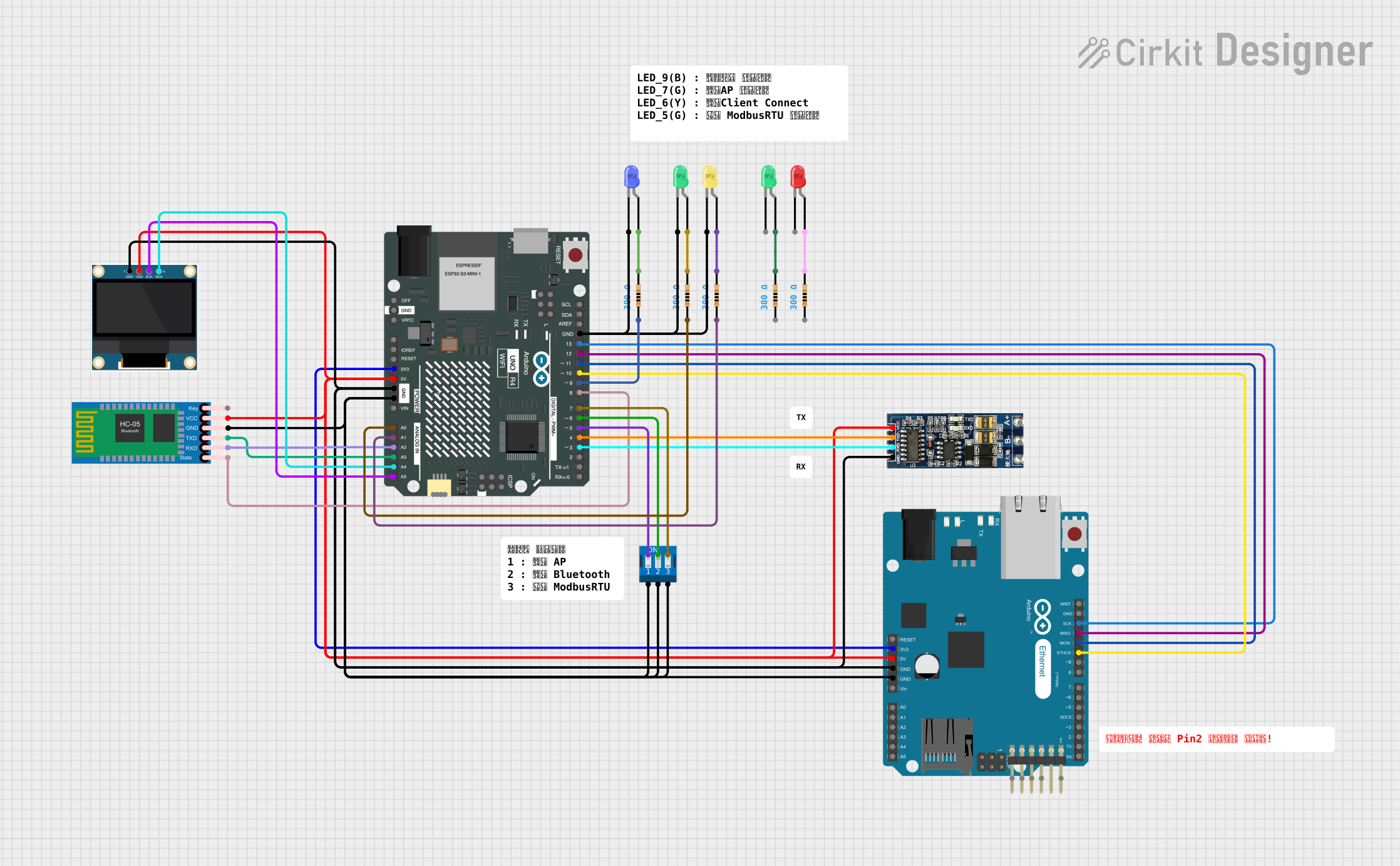
Arduino-Based Multi-Connectivity Interface with Display and Indicators

Circuit Documentation
Summary
The circuit in question appears to be a complex system involving multiple microcontroller boards, an OLED display, a Bluetooth module, an RS485 to TTL converter, and various LEDs with current-limiting resistors. The primary controllers are an Arduino UNO R4 WiFi and an Arduino Board Ethernet, which are interconnected and share power and ground connections. The OLED display is interfaced with the Arduino UNO R4 WiFi for data display, while the HC-05 Bluetooth module and RS485 to TTL converter are used for wireless and wired communication, respectively. The LEDs serve as indicators, and their brightness is controlled by resistors. A DIP switch is included for input selection or mode setting.
Component List
Microcontrollers
- Arduino UNO R4 WiFi: A microcontroller board based on the ATmega328, with WiFi capabilities.
- Arduino Board Ethernet: A microcontroller board similar to the Arduino UNO, with an Ethernet interface.
Display
- 0.96" OLED: A small display for showing data, interfaced via I2C.
Communication Modules
- RS485 to TTL (UART): A module for RS485 communication, interfaced with the Arduino UNO R4 WiFi via UART.
- HC-05 Bluetooth Module: A Bluetooth module for wireless data communication, interfaced with the Arduino UNO R4 WiFi via UART.
Indicators
- LED: Two Pin (blue)
- LED: Two Pin (red)
- LED: Two Pin (green)
- LED: Two Pin (yellow): LEDs used as indicators in the circuit.
Passive Components
- Resistor: A passive component used to limit current, typically to protect LEDs.
Input Devices
- DIP Switch 3 Position: A manual switch used for setting modes or configurations.
Wiring Details
Arduino UNO R4 WiFi
- 3V3: Connected to Arduino Board Ethernet 3V3.
- 5V: Powers the RS485 to TTL converter, HC-05 Bluetooth Module, and 0.96" OLED.
- GND: Common ground with all components.
- A0, A1: Connected to resistors for LED control.
- A2, A3: UART communication with HC-05 Bluetooth Module.
- A4 (SDA), A5 (SCK): I2C communication with 0.96" OLED.
- D3, D4: UART communication with RS485 to TTL converter.
- D5, D6, D7: Connected to DIP Switch 3 Position.
- D8: Reads the state of the HC-05 Bluetooth Module.
- D9: Connected to a resistor for blue LED control.
- D10, D11, D12, D13: SPI communication with Arduino Board Ethernet.
Arduino Board Ethernet
- 3V3, 5V, GND: Shared with Arduino UNO R4 WiFi.
- D10 PWM/SS, D11/MOSI, D12/MISO, D13/SCK: SPI communication with Arduino UNO R4 WiFi.
0.96" OLED
- GND, VDD: Power connections.
- SCK, SDA: I2C communication with Arduino UNO R4 WiFi.
RS485 to TTL (UART)
- GND, VCC: Power connections.
- RXD, TXD: UART communication with Arduino UNO R4 WiFi.
HC-05 Bluetooth Module
- GND, VCC: Power connections.
- TXD, RXD: UART communication with Arduino UNO R4 WiFi.
- State: Connected to Arduino UNO R4 WiFi D8.
LEDs (blue, red, green, yellow)
- Cathode: Connected to GND.
- Anode: Connected to respective resistors.
Resistors
- Pin1: Connected to Arduino UNO R4 WiFi or other LEDs.
- Pin2: Connected to LEDs or other resistors.
DIP Switch 3 Position
- Pins 1, 2, 3: Connected to GND.
- Pins 4, 5, 6: Connected to Arduino UNO R4 WiFi D7, D6, D5 respectively.
Documented Code
No code was provided for the microcontrollers in the circuit. Therefore, this section is left blank until the relevant code is made available.