
Arduino UNO RFID Access Control with Visual and Audio Indicators
View and Edit Project In Cirkit Designer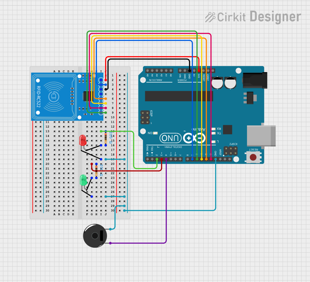
Circuit Documentation
Summary
This document provides a detailed overview of a circuit that integrates an RFID-RC522 module with an Arduino UNO microcontroller. The circuit also includes two LEDs (one red and one green), two resistors, and a piezo buzzer. The RFID-RC522 is used for RFID communication, and the LEDs and buzzer provide visual and auditory feedback, respectively. The Arduino UNO serves as the central processing unit, controlling the RFID reader and the output devices.
Component List
RFID-RC522
- Description: RFID reader/writer module.
- Pins: SDA, SCK, MOSI, MISO, IRQ, GND, RST, 3.3V.
Arduino UNO
- Description: Microcontroller board based on the ATmega328P.
- Pins: UNUSED, IOREF, Reset, 3.3V, 5V, GND, Vin, A0-A5, SCL, SDA, AREF, D0-D13.
Resistor (200 Ohms)
- Description: Passive two-terminal electrical component that implements electrical resistance as a circuit element.
- Properties: Resistance value of 200 Ohms.
LED: Two Pin (red)
- Description: Red light-emitting diode.
- Pins: cathode, anode.
LED: Two Pin (green)
- Description: Green light-emitting diode.
- Pins: cathode, anode.
Piezo Buzzer
- Description: An electronic device that produces a tone or sound when an electric current is passed through it.
- Pins: pin 1, pin 2.
Wiring Details
RFID-RC522
- 3.3V connected to Arduino UNO 3.3V.
- RST connected to Arduino UNO D9.
- GND connected to Arduino UNO GND.
- MISO connected to Arduino UNO D12.
- MOSI connected to Arduino UNO D11.
- SCK connected to Arduino UNO D13.
- SDA connected to Arduino UNO D10.
Arduino UNO
- 3.3V connected to RFID-RC522 3.3V.
- GND connected to common ground with RFID-RC522, both LEDs, and Piezo Buzzer.
- D9 connected to RFID-RC522 RST.
- D12 connected to RFID-RC522 MISO.
- D11 connected to RFID-RC522 MOSI.
- D13 connected to RFID-RC522 SCK.
- D10 connected to RFID-RC522 SDA.
- D2 connected to one end of a 200 Ohm resistor (other end connected to red LED anode).
- D3 connected to one end of a 200 Ohm resistor (other end connected to green LED anode).
- D4 connected to Piezo Buzzer pin 1.
Resistor (200 Ohms)
- One resistor connected between Arduino UNO D2 and red LED anode.
- Another resistor connected between Arduino UNO D3 and green LED anode.
LED: Two Pin (red)
- cathode connected to common ground.
- anode connected to one end of a 200 Ohm resistor (other end connected to Arduino UNO D2).
LED: Two Pin (green)
- cathode connected to common ground.
- anode connected to one end of a 200 Ohm resistor (other end connected to Arduino UNO D3).
Piezo Buzzer
- pin 1 connected to Arduino UNO D4.
- pin 2 connected to common ground.
Documented Code
Arduino UNO Code (sketch.ino)
void setup() {
  // put your setup code here, to run once:

}

void loop() {
  // put your main code here, to run repeatedly:

}
Note: The provided code is a template and does not include specific functionality. It should be populated with the setup and loop functions to control the RFID-RC522, LEDs, and Piezo Buzzer as per the circuit's requirements.