
Arduino UNO Line Following Robot with IR Sensors and L298N Motor Driver
View and Edit Project In Cirkit Designer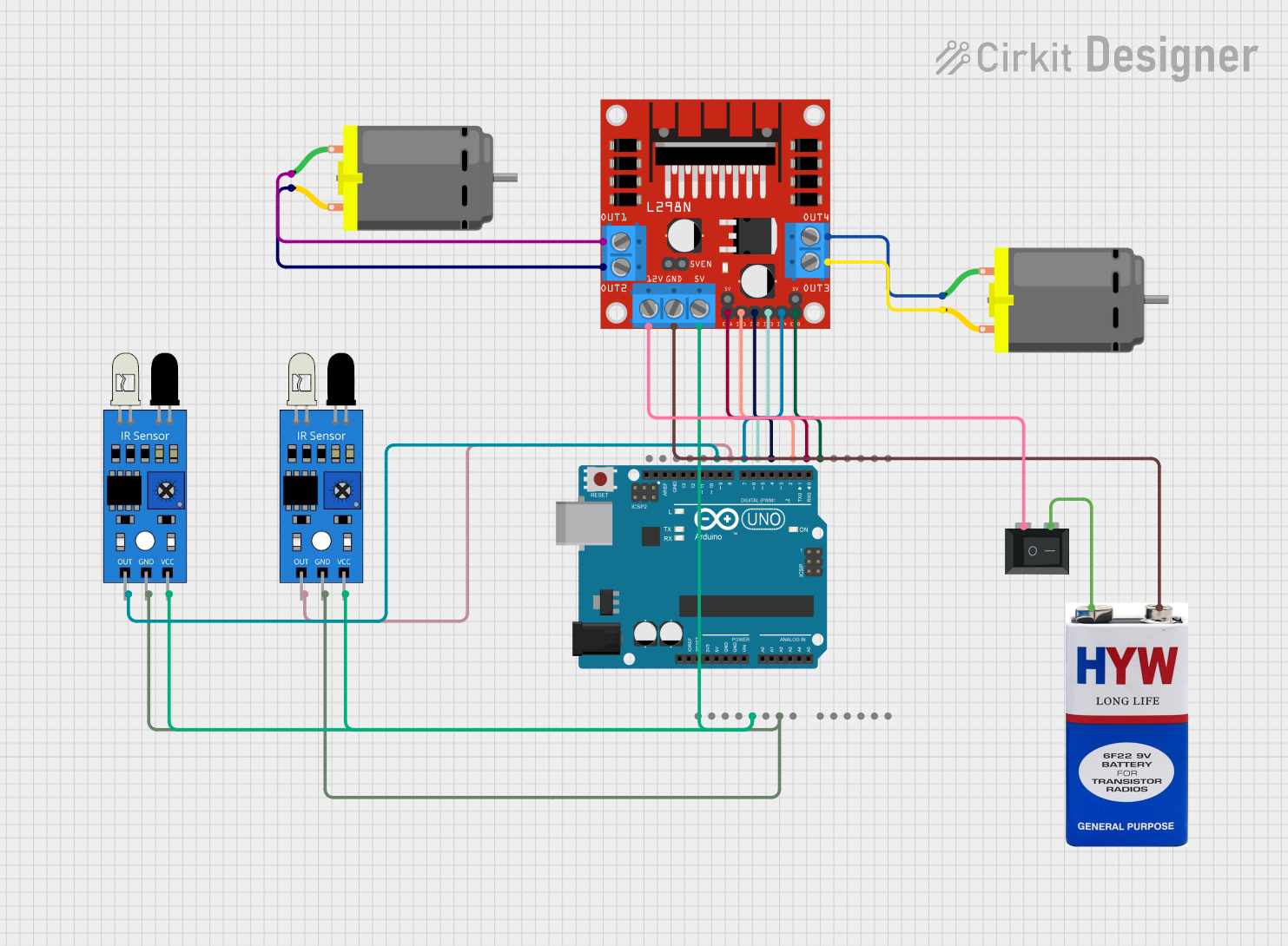
Circuit Documentation
Summary
This circuit is designed to control a robot using an Arduino UNO microcontroller, an L298N DC motor driver, two IR sensors, two DC motors, a 9V battery, and a rocker switch. The robot uses the IR sensors to detect lines and adjusts the motor speeds accordingly to follow the line.
Component List
Arduino UNO
- Description: A microcontroller board based on the ATmega328P.
- Pins: UNUSED, IOREF, Reset, 3.3V, 5V, GND, Vin, A0, A1, A2, A3, A4, A5, SCL, SDA, AREF, D13, D12, D11, D10, D9, D8, D7, D6, D5, D4, D3, D2, D1, D0
L298N DC Motor Driver
- Description: A dual H-Bridge motor driver that allows control of two DC motors.
- Pins: OUT1, OUT2, 12V, GND, 5V, OUT3, OUT4, 5V-ENA-JMP-I, 5V-ENA-JMP-O, +5V-J1, +5V-J2, ENA, IN1, IN2, IN3, IN4, ENB
IR Sensor (Right)
- Description: An infrared sensor used for line detection.
- Pins: out, gnd, vcc
IR Sensor (Left)
- Description: An infrared sensor used for line detection.
- Pins: out, gnd, vcc
DC Motor (Right)
- Description: A DC motor used to drive the right wheel of the robot.
- Pins: pin 1, pin 2
DC Motor (Left)
- Description: A DC motor used to drive the left wheel of the robot.
- Pins: pin 1, pin 2
9V Battery
- Description: A power source for the circuit.
- Pins: +, -
Rocker Switch (SPST)
- Description: A single-pole single-throw switch used to control the power supply.
- Pins: 1, 2
Wiring Details
Arduino UNO
5V connected to:
- L298N DC Motor Driver (5V)
- IR Sensor (Right) (vcc)
- IR Sensor (Left) (vcc)
GND connected to:
- IR Sensor (Right) (gnd)
- IR Sensor (Left) (gnd)
D12 connected to:
- IR Sensor (Left) (out)
D11 connected to:
- IR Sensor (Right) (out)
D10 connected to:
- L298N DC Motor Driver (IN4)
D9 connected to:
- L298N DC Motor Driver (IN3)
D8 connected to:
- L298N DC Motor Driver (IN2)
D7 connected to:
- L298N DC Motor Driver (IN1)
D6 connected to:
- L298N DC Motor Driver (ENA)
D5 connected to:
- L298N DC Motor Driver (ENB)
L298N DC Motor Driver
OUT1 connected to:
- DC Motor (Right) (pin 1)
OUT2 connected to:
- DC Motor (Right) (pin 2)
OUT3 connected to:
- DC Motor (Left) (pin 2)
OUT4 connected to:
- DC Motor (Left) (pin 1)
12V connected to:
- Rocker Switch (SPST) (1)
GND connected to:
- 9V Battery (-)
IR Sensor (Right)
vcc connected to:
- Arduino UNO (5V)
gnd connected to:
- Arduino UNO (GND)
out connected to:
- Arduino UNO (D11)
IR Sensor (Left)
vcc connected to:
- Arduino UNO (5V)
gnd connected to:
- Arduino UNO (GND)
out connected to:
- Arduino UNO (D12)
DC Motor (Right)
pin 1 connected to:
- L298N DC Motor Driver (OUT1)
pin 2 connected to:
- L298N DC Motor Driver (OUT2)
DC Motor (Left)
pin 1 connected to:
- L298N DC Motor Driver (OUT4)
pin 2 connected to:
- L298N DC Motor Driver (OUT3)
9V Battery
+ connected to:
- Rocker Switch (SPST) (2)
- connected to:
- L298N DC Motor Driver (GND)
Rocker Switch (SPST)
1 connected to:
- L298N DC Motor Driver (12V)
2 connected to:
- 9V Battery (+)
Documented Code
#define IR_SENSOR_RIGHT 11
#define IR_SENSOR_LEFT 12
#define MOTOR_SPEED 180

//Right motor
int enableRightMotor=6;
int rightMotorPin1=7;
int rightMotorPin2=8;

//Left motor
int enableLeftMotor=5;
int leftMotorPin1=9;
int leftMotorPin2=10;

void setup()
{
  //The problem with TT gear motors is that, at very low pwm value it does not even rotate.
  //If we increase the PWM value then it rotates faster and our robot is not controlled in that speed and goes out of line.
  //For that we need to increase the frequency of analogWrite.
  //Below line is important to change the frequency of PWM signal on pin D5 and D6
  //Because of this, motor runs in controlled manner (lower speed) at high PWM value.
  //This sets frequecny as 7812.5 hz.
  TCCR0B = TCCR0B & B11111000 | B00000010 ;

  // put your setup code here, to run once:
  pinMode(enableRightMotor, OUTPUT);
  pinMode(rightMotorPin1, OUTPUT);
  pinMode(rightMotorPin2, OUTPUT);

  pinMode(enableLeftMotor, OUTPUT);
  pinMode(leftMotorPin1, OUTPUT);
  pinMode(leftMotorPin2, OUTPUT);

  pinMode(IR_SENSOR_RIGHT, INPUT);
  pinMode(IR_SENSOR_LEFT, INPUT);
  rotateMotor(0,0);
}

void loop()
{
  int rightIRSensorValue = digitalRead(IR_SENSOR_RIGHT);
  int leftIRSensorValue = digitalRead(IR_SENSOR_LEFT);

  //If none of the sensors detects black line, then go straight
  if (rightIRSensorValue == LOW && leftIRSensorValue == LOW)
  {
    rotateMotor(MOTOR_SPEED, MOTOR_SPEED);
  }
  //If right sensor detects black line, then turn right
  else if (rightIRSensorValue == HIGH && leftIRSensorValue == LOW )
  {
      rotateMotor(-MOTOR_SPEED, MOTOR_SPEED);
  }
  //If left sensor detects black line, then turn left
  else if (rightIRSensorValue == LOW && leftIRSensorValue == HIGH )
  {
      rotateMotor(MOTOR_SPEED, -MOTOR_SPEED);
  }
  //If both the sensors detect black line, then stop
  else
  {
    rotateMotor(0, 0);
  }
}

void rotateMotor(int rightMotorSpeed, int leftMotorSpeed)
{
  if (rightMotorSpeed < 0)
  {
    digitalWrite(rightMotorPin1,LOW);
    digitalWrite(rightMotorPin2,HIGH);
  }
  else if (rightMotorSpeed > 0)
  {
    digitalWrite(rightMotorPin1,HIGH);
    digitalWrite(rightMotorPin2,LOW);
  }
  else
  {
    digitalWrite(rightMotorPin1,LOW);
    digitalWrite(rightMotorPin2,LOW);
  }

  if (leftMotorSpeed < 0)
  {
    digitalWrite(leftMotorPin1,LOW);
    digitalWrite(leftMotorPin2,HIGH);
  }
  else if (leftMotorSpeed > 0)
  {
    digitalWrite(leftMotorPin1,HIGH);
    digitalWrite(leftMotorPin2,LOW);
  }
  else
  {
    digitalWrite(leftMotorPin1,LOW);
    digitalWrite(leftMotorPin2,LOW);
  }
  analogWrite(enableRightMotor, abs(rightMotorSpeed));
  analogWrite(enableLeftMotor, abs(leftMotorSpeed));
}