
Arduino UNO Based Solar Tracking System with DHT11 Sensor and OLED Display
View and Edit Project In Cirkit Designer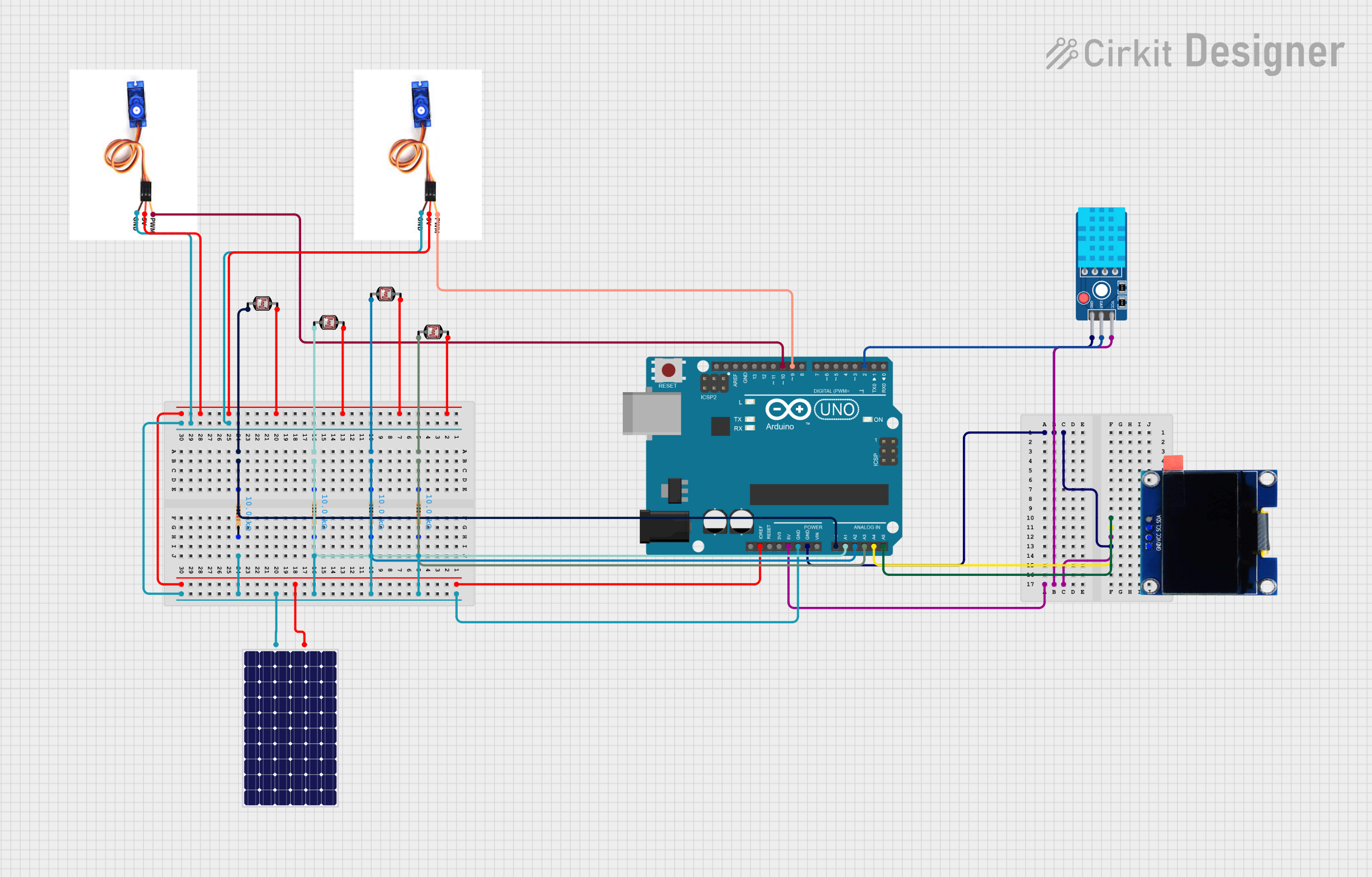
Solar Tracker Circuit with DHT11 and OLED Display Documentation
Summary
This circuit is designed to control a solar tracking system using two SG90 servo motors. It utilizes photoresistors to detect solar light intensity, a DHT11 sensor to measure temperature and humidity, and an OLED display to show the solar panel voltage and environmental data. The system is controlled by an Arduino UNO microcontroller, which processes the sensor inputs and drives the servo motors to adjust the solar panel's position for optimal sunlight exposure.
Component List
DHT11 Sensor V2
- Description: A digital temperature and humidity sensor.
- Pins: GND, DAT, VCC
OLED 1.3" Display
- Description: A small display for showing data such as temperature, humidity, and solar voltage.
- Pins: GND, VCC, SCL, SDA
Arduino UNO
- Description: A microcontroller board based on the ATmega328P.
- Pins: UNUSED, IOREF, Reset, 3.3V, 5V, GND, Vin, A0-A5, SCL, SDA, AREF, D0-D13
SG90 Servo Motor
- Description: A small and lightweight servo motor for precise control.
- Pins: PWM, 5V, GND
Resistor (10k Ohms)
- Description: A resistor with a resistance of 10,000 Ohms.
- Pins: pin1, pin2
Photocell (LDR)
- Description: A light-dependent resistor used to detect light intensity.
- Pins: pin 0, pin 1
Solar Panel
- Description: A small solar panel used to generate voltage from sunlight.
- Pins: +, -
Wiring Details
DHT11 Sensor V2
- GND: Connected to Arduino UNO GND
- DAT: Connected to Arduino UNO Digital Pin 2
- VCC: Connected to Arduino UNO 5V
OLED 1.3" Display
- GND: Connected to Arduino UNO GND
- VCC: Connected to Arduino UNO 5V
- SCL: Connected to Arduino UNO Analog Pin 4
- SDA: Connected to Arduino UNO Analog Pin 5
SG90 Servo Motor
- PWM: One servo connected to Arduino UNO Digital Pin 9, another to Digital Pin 10
- 5V: Connected to Arduino UNO 5V
- GND: Connected to Arduino UNO GND
Resistor (10k Ohms)
- pin1: Connected to Arduino UNO Analog Pins A0, A1, A2, A3 (one resistor per pin)
- pin2: Connected to Arduino UNO GND
Photocell (LDR)
- pin 0: Connected to Arduino UNO Analog Pins A0, A1, A2, A3 (one LDR per pin)
- pin 1: Connected to Arduino UNO 5V through a 10k Ohm resistor
Solar Panel
- +: Connected to Arduino UNO IOREF
- -: Connected to Arduino UNO GND
Documented Code
/*
 * Arduino Sketch for Solar Tracker with DHT11 and OLED Display
 *
 * This code controls a solar tracking system using two SG90 servo motors,
 * detects solar light intensity using photoresistors, displays temperature
 * and humidity using a DHT11 sensor, and shows voltage from a solar panel
 * on an OLED display.
 */

#include <Servo.h>
#include <Wire.h>
#include <Adafruit_GFX.h>
#include <Adafruit_SSD1306.h>
#include <DHT.h>

#define DHTPIN 2          // Digital pin connected to the DHT sensor
#define DHTTYPE DHT11     // DHT 11 type
#define OLED_RESET -1     // OLED display reset pin (not used)
Adafruit_SSD1306 display(OLED_RESET);

Servo servo1;             // Servo motor for horizontal movement
Servo servo2;             // Servo motor for vertical movement
DHT dht(DHTPIN, DHTTYPE); // DHT sensor object

// LDR pins connected to analog inputs
const int ldrPin1 = A0;
const int ldrPin2 = A1;
const int ldrPin3 = A2;
const int ldrPin4 = A3;

// Servo pins connected to digital outputs
const int servoPin1 = 9;
const int servoPin2 = 10;

// Solar panel voltage pin connected to analog input
const int solarPin = A4;

void setup() {
  servo1.attach(servoPin1); // Attach servo1 to its control pin
  servo2.attach(servoPin2); // Attach servo2 to its control pin
  dht.begin();              // Initialize the DHT sensor
  display.begin(SSD1306_SWITCHCAPVCC, 0x3C); // Initialize the OLED display
  display.display();        // Show initial display buffer
  delay(2000);              // Wait for 2 seconds
  display.clearDisplay();   // Clear the display buffer
}

void loop() {
  // Read values from the LDRs
  int ldr1 = analogRead(ldrPin1);
  int ldr2 = analogRead(ldrPin2);
  int ldr3 = analogRead(ldrPin3);
  int ldr4 = analogRead(ldrPin4);

  // Read the solar panel voltage
  int solarVoltage = analogRead(solarPin);

  // Read temperature and humidity from the DHT sensor
  float temperature = dht.readTemperature();
  float humidity = dht.readHumidity();

  // Calculate the difference in light between pairs of LDRs
  int error1 = ldr1 - ldr2;
  int error2 = ldr3 - ldr4;

  // Map the error values to servo positions
  int servo1Pos = map(error1, -1023, 1023, 0, 180);
  int servo2Pos = map(error2, -1023, 1023, 0, 180);

  // Write the servo positions
  servo1.write(servo1Pos);
  servo2.write(servo2Pos);

  // Display the temperature, humidity, and solar voltage on the OLED
  display.clearDisplay();
  display.setTextSize(1);
  display.setTextColor(WHITE);
  display.setCursor(0,0);
  display.print("Temp: ");
  display.print(temperature);
  display.print(" C");
  display.setCursor(0,10);
  display.print("Humidity: ");
  display.print(humidity);
  display.print(" %");
  display.setCursor(0,20);
  display.print("Solar V: ");
  display.print(solarVoltage * (5.0 / 1023.0));
  display.print(" V");
  display.display();

  delay(2000); // Wait for 2 seconds before the next loop iteration
}
This code is responsible for reading sensor data, controlling the servo motors based on the light intensity detected by the LDRs, and displaying the temperature, humidity, and solar panel voltage on the OLED display. The setup() function initializes the components, and the loop() function contains the main logic that is executed repeatedly.