
Arduino Mega 2560 Smart Home Automation System with Sensor Integration
View and Edit Project In Cirkit Designer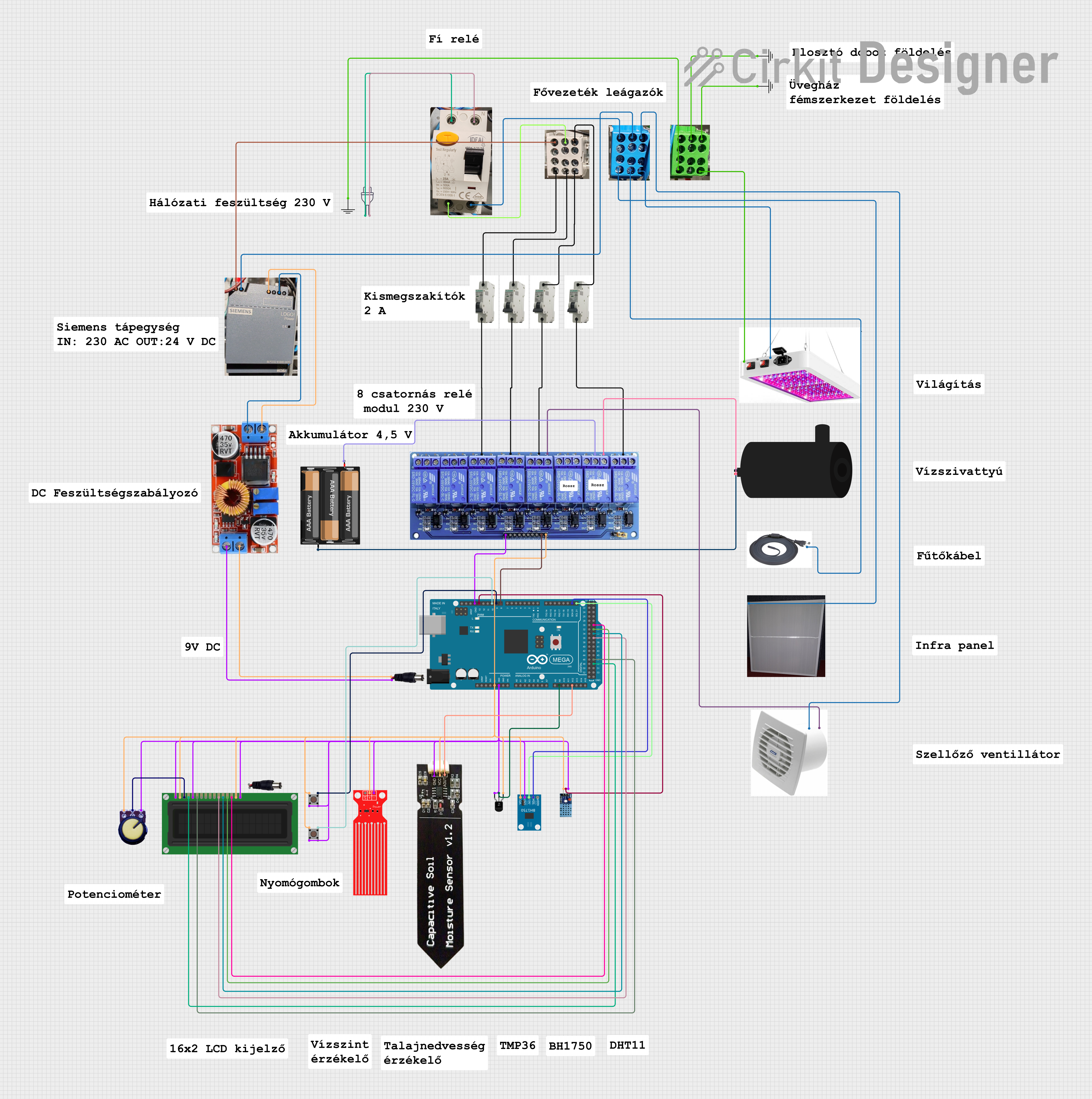
Circuit Documentation
Summary
This circuit is designed using an Arduino Mega 2560 microcontroller to interface with various sensors and actuators. The circuit includes temperature and humidity sensors, a light sensor, an LCD display, pushbuttons, a relay module, and other components. The Arduino Mega 2560 reads data from the sensors and controls the actuators based on the sensor inputs.
Component List
Arduino Mega 2560
- Description: A microcontroller board based on the ATmega2560.
- Pins: IOREF, RESET, 3V3, 5V, GND, VIN, A0-A15, D0-D53, PWM, AREF, SDA, SCL
DHT 11
- Description: A temperature and humidity sensor.
- Pins: VCC, GND, DATA
BH1750
- Description: A light intensity sensor.
- Pins: VCC, GND, SCL, SDA, ADDR
Temperature Sensor (LM35)
- Description: An analog temperature sensor.
- Pins: +Vs, Vout, GND
LCD Display (16 pin)
- Description: A 16x2 character LCD display.
- Pins: VSS, VDD, VO, RS, R_W, E, DB0-DB7, A, K
Pushbutton
- Description: A simple pushbutton switch.
- Pins: Pin 1 (in), Pin 2 (in), Pin 3 (out), Pin 4 (out)
MCB
- Description: Miniature Circuit Breaker.
- Pins: IN, OUT
Fí Relé 2
- Description: Residual-current device (RCD).
- Pins: None
Eloszto +
- Description: Positive power distribution block.
- Pins: None
Eloszto -
- Description: Negative power distribution block.
- Pins: None
Eloszto Föld
- Description: Ground distribution block.
- Pins: None
GND
- Description: Ground connection.
- Pins: GND
Fűtőkábel
- Description: Heating cable.
- Pins: None
Lámpa
- Description: Lamp.
- Pins: -, +, GND
Szellőző
- Description: Ventilator.
- Pins: GND, +
Power Jack
- Description: Power jack for external power supply.
- Pins: POSITIF, NEGATIF
Water Level Sensor
- Description: Water level sensor.
- Pins: SIG, VCC, GND
Water Pump
- Description: Water pump.
- Pins: positive, negative
Infra Panel 50 W
- Description: Infrared heating panel.
- Pins: -, +
Siemens DIN-sín tápellátás
- Description: DIN rail power supply.
- Pins: +, -
Potentiometer
- Description: Variable resistor.
- Pins: GND, Output, VCC
8 Channel Relay JD-VCC
- Description: Relay module with 8 channels.
- Pins: JD-VCC, VCC, GND, In1-In8, IN1_NC, IN1_COM, IN1_NO, IN2_NC, IN2_COM, IN2_NO, IN3_NC, IN3_COM, IN3_NO, IN4_NC, IN4_COM, IN4_NO, IN5_NC, IN5_COM, IN5_NO, IN6_NC, IN6_COM, IN6_NO, IN7_NC, IN7_COM, IN7_NO, IN8_NC, IN8_COM, IN8_NO
Capasitive Soil Moisture Sensor V1.2
- Description: Capacitive soil moisture sensor.
- Pins: GND, VCC, AOUT
3xAABattery
- Description: Battery pack with 3 AA batteries.
- Pins: VCC, GND
Regulator Stepdown DC XL4015 CC CV
- Description: DC-DC step-down voltage regulator.
- Pins: IN +, IN -, OUT +, OUT -
Wiring Details
Arduino Mega 2560
- 5V: Connected to VCC of DHT 11, BH1750, Temperature Sensor (LM35), LCD Display (VDD, A), Pushbuttons (Pin 1), Potentiometer (VCC), Water Level Sensor, Capacitive Soil Moisture Sensor, 8 Channel Relay JD-VCC
- GND: Connected to GND of DHT 11, BH1750, Temperature Sensor (LM35), LCD Display (VSS, K, R_W), Pushbuttons (Pin 2), Potentiometer (GND), Water Level Sensor, Capacitive Soil Moisture Sensor, 8 Channel Relay JD-VCC
- A9: Connected to Vout of Temperature Sensor (LM35)
- A12: Connected to AOUT of Capacitive Soil Moisture Sensor
- D21/SCL: Connected to SCL of BH1750
- D20/SDA: Connected to SDA of BH1750
- D8 PWM: Connected to In8 of 8 Channel Relay JD-VCC
- D9 PWM: Connected to Pin 3 (out) of Pushbutton
- D10 PWM: Connected to Pin 3 (out) of Pushbutton
- D13 PWM: Connected to DATA of DHT 11
- D49: Connected to RS of LCD Display
- D47: Connected to E of LCD Display
- D37: Connected to DB4 of LCD Display
- D35: Connected to DB5 of LCD Display
- D33: Connected to DB6 of LCD Display
- D31: Connected to DB7 of LCD Display
DHT 11
- VCC: Connected to 5V of Arduino Mega 2560
- GND: Connected to GND of Arduino Mega 2560
- DATA: Connected to D13 PWM of Arduino Mega 2560
BH1750
- VCC: Connected to 5V of Arduino Mega 2560
- GND: Connected to GND of Arduino Mega 2560
- SCL: Connected to D21/SCL of Arduino Mega 2560
- SDA: Connected to D20/SDA of Arduino Mega 2560
Temperature Sensor (LM35)
- +Vs: Connected to 5V of Arduino Mega 2560
- Vout: Connected to A9 of Arduino Mega 2560
- GND: Connected to GND of Arduino Mega 2560
LCD Display (16 pin)
- VSS: Connected to GND of Arduino Mega 2560
- VDD: Connected to 5V of Arduino Mega 2560
- VO: Connected to Output of Potentiometer
- RS: Connected to D49 of Arduino Mega 2560
- R_W: Connected to GND of Arduino Mega 2560
- E: Connected to D47 of Arduino Mega 2560
- DB4: Connected to D37 of Arduino Mega 2560
- DB5: Connected to D35 of Arduino Mega 2560
- DB6: Connected to D33 of Arduino Mega 2560
- DB7: Connected to D31 of Arduino Mega 2560
- A: Connected to 5V of Arduino Mega 2560
- K: Connected to GND of Arduino Mega 2560
Pushbutton
- Pin 1 (in): Connected to 5V of Arduino Mega 2560
- Pin 2 (in): Connected to GND of Arduino Mega 2560
- Pin 3 (out): Connected to D9 PWM of Arduino Mega 2560
- Pin 3 (out): Connected to D10 PWM of Arduino Mega 2560
8 Channel Relay JD-VCC
- VCC: Connected to 5V of Arduino Mega 2560
- GND: Connected to GND of Arduino Mega 2560
- In8: Connected to D8 PWM of Arduino Mega 2560
- IN3_COM: Connected to IN of MCB
- IN4_COM: Connected to IN of MCB
- IN5_COM: Connected to IN of MCB
- IN5_NO: Connected to + of Szellőző
- IN7_COM: Connected to VCC of 3xAABattery
- IN7_NO: Connected to positive of Water Pump
- IN8_COM: Connected to IN of MCB
Potentiometer
- **V