
Arduino-Controlled Smart Home System with Solar Charging and Bluetooth Connectivity
View and Edit Project In Cirkit Designer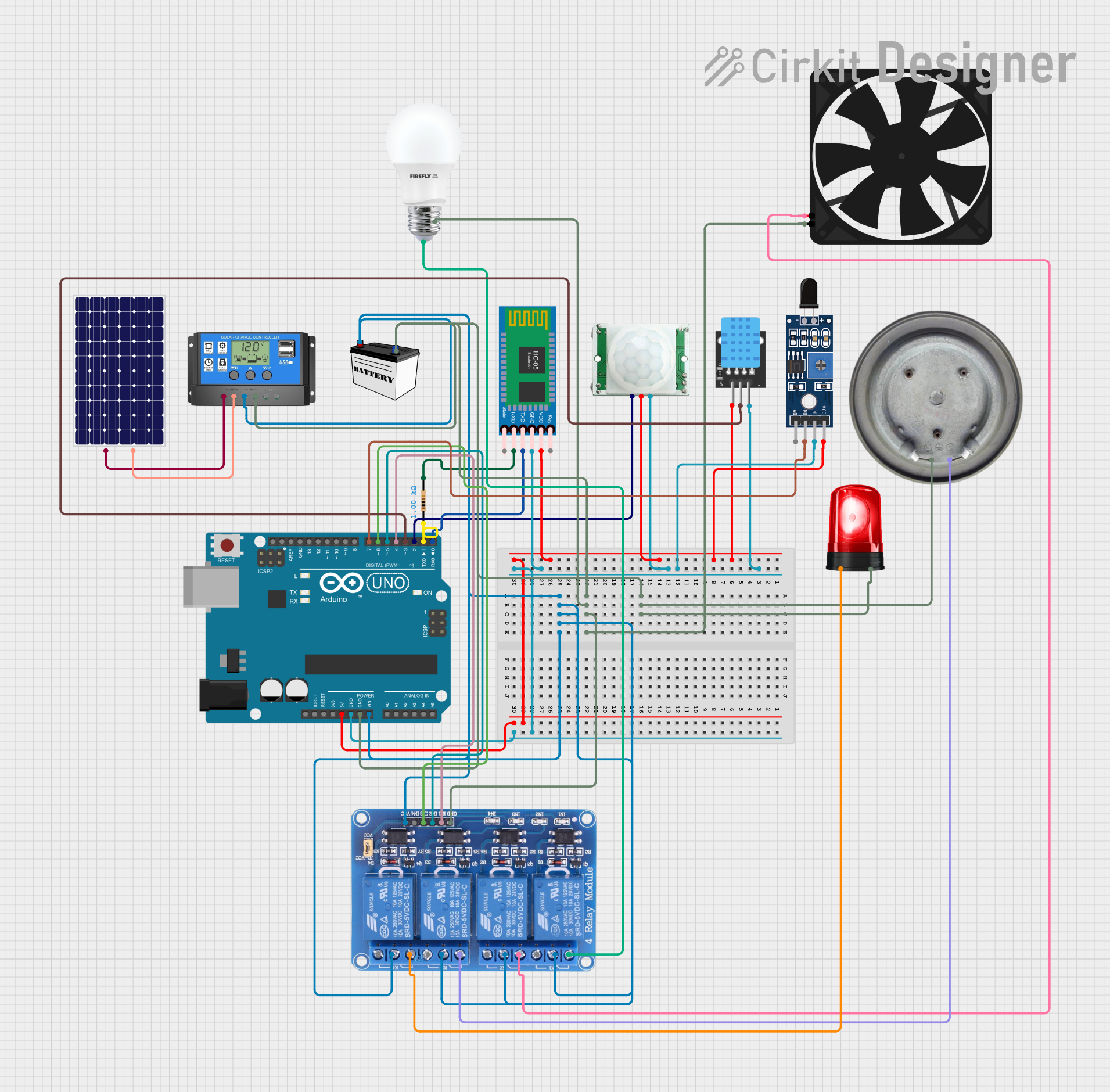
Circuit Documentation
Summary
This circuit is designed to integrate various components including a microcontroller, sensors, a relay module, a Bluetooth module, and power supply elements to create a system capable of sensing, processing, and actuating based on the inputs from the sensors. The Arduino UNO serves as the central processing unit, interfacing with a PIR motion sensor, a DHT11 temperature and humidity sensor, a flame sensor, and a Bluetooth module for wireless communication. The relay module is used to control power to a bulb, fan, heater element, and siren. Power is supplied by a solar panel charging a 12V battery through a solar charge controller.
Component List
BULB
- A simple light bulb that turns on or off based on the control signal from the relay module.
HC-05 Bluetooth Module
- A wireless communication module that allows the Arduino to communicate with other Bluetooth-enabled devices.
Arduino UNO
- A microcontroller board based on the ATmega328P, used for processing sensor data and controlling other components in the circuit.
PIR/Motion Sensor
- A sensor that detects motion in the environment and sends a signal to the Arduino.
Resistor (1000 Ohms)
- A resistor with a resistance of 1000 Ohms, used for current limiting or voltage division in the circuit.
Solar Panel
- A photovoltaic panel that converts sunlight into electrical energy to charge the battery.
Solar Charge Controller
- A device that regulates the voltage and current coming from the solar panels going to the battery.
12V Battery (Small Size)
- A rechargeable battery that provides power to the circuit.
Relay 4 Channel 5v
- A 4-channel relay module that allows the Arduino to control high power devices such as the bulb, fan, heater, and siren.
Fan
- An electric fan that can be turned on or off by the relay module.
KY-015 DHT11
- A sensor module for measuring temperature and humidity in the environment.
Heater Element
- An electrical device that generates heat, controlled by the relay module.
Sensor SHT113 Flame
- A sensor that detects the presence of a flame or fire and sends a signal to the Arduino.
Siren
- An audible alarm device that can be activated by the relay module.
Wiring Details
BULB
- Negative (-) connected to the common ground net.
- Positive (+) connected to the normally closed (NC1) contact of the relay module.
HC-05 Bluetooth Module
- Key not connected.
- VCC connected to the 5V net from the Arduino.
- TXD connected to the D0 pin of the Arduino.
- RXD connected to a 1000 Ohm resistor, which is then connected to the D1 pin of the Arduino.
- State not connected.
- GND connected to the common ground net.
Arduino UNO
- UNUSED pins not connected.
- IOREF, Reset, 3.3V, AREF, D13-D8 not connected.
- 5V connected to the 5V net supplying power to various components.
- GND connected to the common ground net.
- Vin connected to the Battery + net from the solar charge controller.
- A0-A5, SCL, SDA not connected.
- D7 connected to the D0 pin of the flame sensor.
- D6 connected to the IN3 of the relay module.
- D5 connected to the IN2 of the relay module.
- D4 connected to the IN1 of the relay module.
- D3 connected to the signal (S) pin of the DHT11 sensor.
- D2 connected to the VCC pin of the PIR motion sensor.
- D1 connected to the other end of the 1000 Ohm resistor connected to the RXD pin of the Bluetooth module.
- D0 connected to the TXD pin of the Bluetooth module.
PIR/Motion Sensor
- GND connected to the common ground net.
- OUTPUT connected to the 5V net.
- VCC connected to the D2 pin of the Arduino.
Resistor (1000 Ohms)
- Pin1 connected to the RXD pin of the Bluetooth module.
- Pin2 connected to the D1 pin of the Arduino.
Solar Panel
- Positive (+) connected to the Solar Cell + net of the solar charge controller.
- Negative (-) connected to the Solar Cell - net of the solar charge controller.
Solar Charge Controller
- Solar Cell + connected to the positive (+) of the solar panel.
- Solar Cell - connected to the negative (-) of the solar panel.
- Battery + connected to the VCC net of the relay module and Vin of the Arduino.
- Battery - connected to the common ground net.
- Load + not connected.
- Load - not connected.
12V Battery (Small Size)
- VCC connected to the Battery + net of the solar charge controller.
- GND connected to the common ground net.
Relay 4 Channel 5v
- GND connected to the common ground net.
- IN1 connected to the D4 pin of the Arduino.
- IN2 connected to the D5 pin of the Arduino.
- IN3 connected to the D6 pin of the Arduino.
- IN4 not connected.
- VCC connected to the Battery + net of the solar charge controller.
- COM1-COM4 connected to the Battery + net of the solar charge controller.
- NO1-NO4 not connected.
- NC1 connected to the positive (+) of the bulb.
- NC2 connected to the 5V pin of the fan.
- NC3 connected to the VCC pin of the heater element.
- NC4 connected to the Positive pin of the siren.
Fan
- GND connected to the common ground net.
- 5V connected to the normally closed (NC2) contact of the relay module.
KY-015 DHT11
- 5V connected to the 5V net.
- S connected to the D3 pin of the Arduino.
- GND connected to the common ground net.
Heater Element
- VCC connected to the normally closed (NC3) contact of the relay module.
- GND connected to the common ground net.
Sensor SHT113 Flame
- A0 not connected.
- D0 connected to the D7 pin of the Arduino.
- GND connected to the common ground net.
- VCC connected to the 5V net.
Siren
- Positive connected to the normally closed (NC4) contact of the relay module.
- Ground connected to the common ground net.
Documented Code
Arduino UNO Code (sketch.ino)
void setup() {
  // put your setup code here, to run once:

}

void loop() {
  // put your main code here, to run repeatedly:

}
Note: The provided code is a template and does not include specific functionality. It needs to be filled in with the logic to read sensors, control the relay module, and communicate via Bluetooth based on the requirements of the circuit's application.