Arduino-Controlled Traffic Light Simulator with Joystick Interaction
Circuit Documentation
Summary of the Circuit
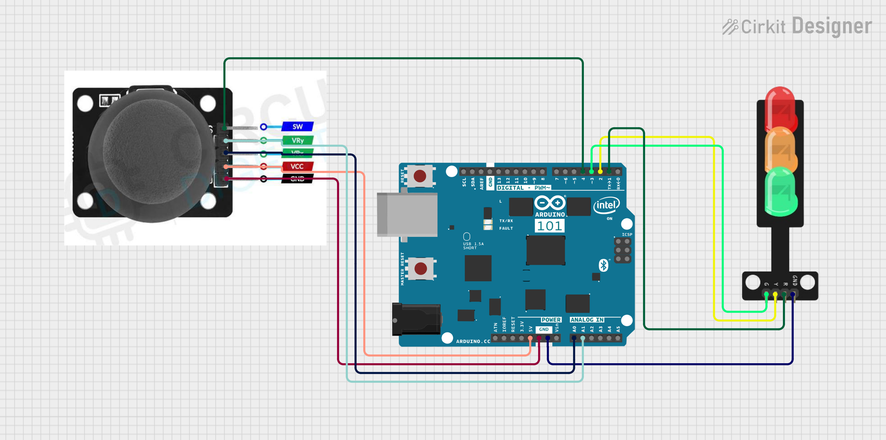
This circuit is designed to interface a joystick module with an Arduino 101 microcontroller to control a traffic light system. The joystick's position is read by the Arduino's analog inputs, and the microcontroller outputs signals to control the green, yellow, and red lights of the traffic light. The joystick also includes a switch that is connected to a digital input on the Arduino for additional input functionality. The circuit is powered through the Arduino, which provides a common ground and 5V supply to the joystick module.
Component List
Traffic Light
- Pins: Green, Yellow, Red, GND
- Description: A traffic light component with three LEDs representing the green, yellow, and red lights.
Arduino 101
- Pins: A5/SCL, A4/SDA, AREF, GND, D13/SCK, D12/MISO, D11 PWM/MOSI, D10 PWM/SS, D9 PWM, D8, D7, D6 PWM, D5 PWM, D4, D3 PWM, D2, D1/TX, D0/RX, AIN, ioref, RESET, 3V3, 5V, VIN, A0, A1, A2, A3, ICSP MISO, ICSP SCK, ICSP MOSI
- Description: A microcontroller board based on the Intel Curie module, designed for IoT applications with built-in Bluetooth and 6-axis accelerometer/gyroscope.
Joystick Module
- Pins: SW, VRY, VRX, VCC, GND
- Description: A module that provides a two-axis thumb joystick with an integrated push-button switch (SW).
Wiring Details
Traffic Light
- Green LED: Connected to Arduino 101's D3 PWM
- Yellow LED: Connected to Arduino 101's D2
- Red LED: Connected to Arduino 101's D1/TX
- GND: Shared ground with Arduino 101
Arduino 101
- 5V: Provides power to the Joystick module's VCC
- GND: Common ground for Traffic Light and Joystick module
- D3 PWM: Controls the Green LED of the Traffic Light
- D2: Controls the Yellow LED of the Traffic Light
- D1/TX: Controls the Red LED of the Traffic Light
- D4: Reads the state of the Joystick module's switch (SW)
- A0: Reads the X-axis value from the Joystick module (VRX)
- A1: Reads the Y-axis value from the Joystick module (VRY)
Joystick Module
- SW: Connected to Arduino 101's D4
- VRY: Connected to Arduino 101's A1
- VRX: Connected to Arduino 101's A0
- VCC: Powered by Arduino 101's 5V
- GND: Shared ground with Arduino 101
Documented Code
void setup() {
  // put your setup code here, to run once:

}

void loop() {
  // put your main code here, to run repeatedly:

}
Filename: sketch.ino
Note: The provided code is a template and does not contain any functional code to operate the traffic light or read the joystick inputs. The user is expected to fill in the setup and loop functions with the appropriate initialization and control logic.