Cirkit Designer
Your all-in-one circuit design IDE
Home /
Project Documentation
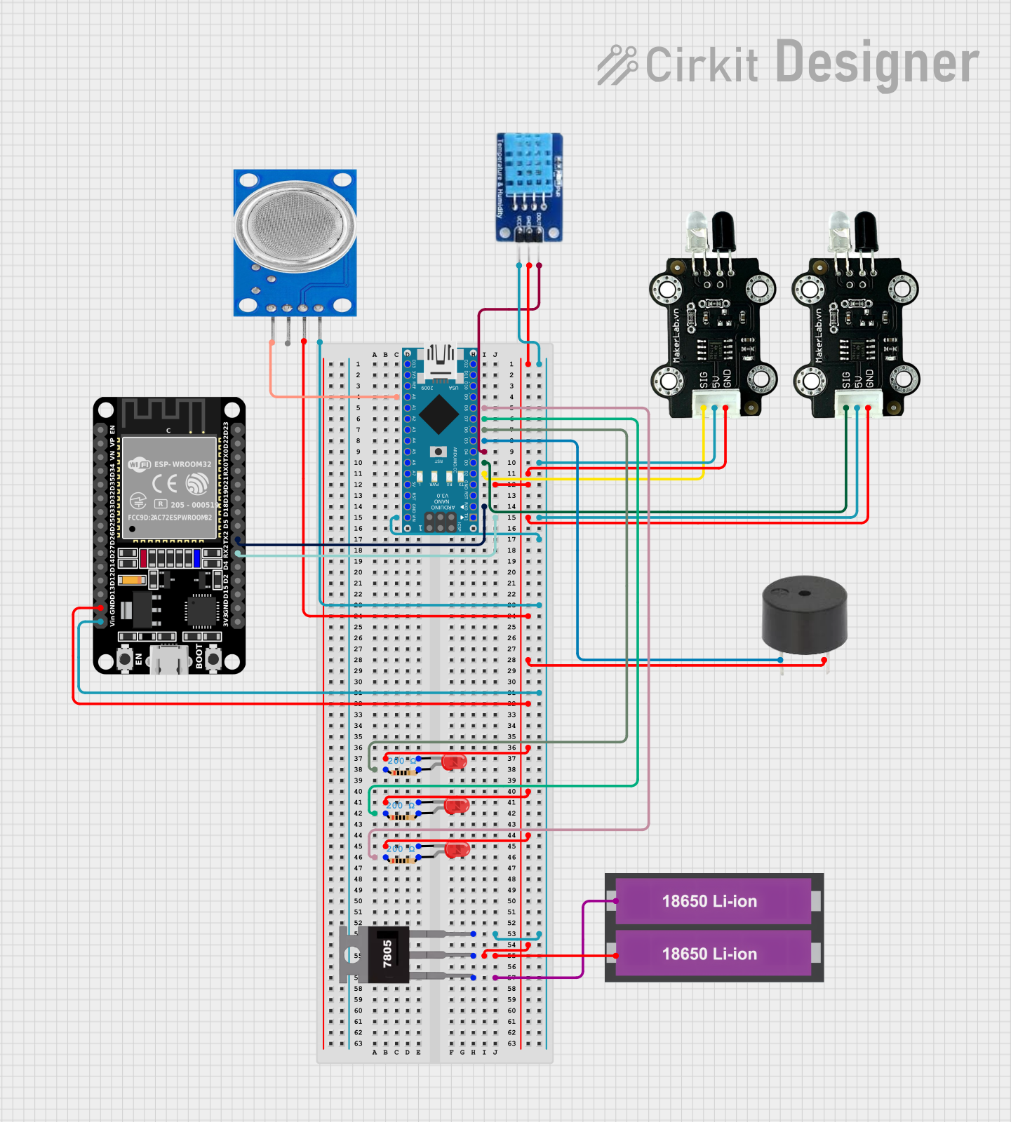
Arduino Nano and ESP32-Based Smart Environmental Monitoring System with Battery Power
Circuit Documentation
Summary
This document provides a detailed overview of a circuit that includes various sensors, LEDs, a buzzer, a microcontroller, and a power supply. The circuit is designed to interface with an Arduino Nano and an ESP32 microcontroller, and it includes components such as infrared sensors, a temperature and humidity sensor, a gas sensor, and multiple LEDs. The circuit is powered by two 18650 Li-ion batteries regulated by a 7805 voltage regulator.
Component List
MKE-S11 IR Infrared Obstacle Avoidance Sensor
- Pins: SIG, 5V, GND
- Description: Infrared sensor used for obstacle detection.
DHT11
- Pins: DATA, GND, VCC
- Description: Temperature and humidity sensor.
18650 Li-ion Battery x 2
- Pins: +, -
- Description: Power supply for the circuit.
ESP32 (30 pin)
- Pins: EN, VP, VN, D34, D35, D32, D33, D25, D26, D27, D14, D12, D13, GND, Vin, D23, D22, TX0, RX0, D21, D19, D18, D5, TX2, RX2, D4, D2, D15, 3V3
- Description: Microcontroller with Wi-Fi and Bluetooth capabilities.
MQ135
- Pins: VCC, GND, A0, D0
- Description: Gas sensor for air quality monitoring.
7805
- Pins: Vin, Gnd, Vout
- Description: Voltage regulator to provide a stable 5V output.
Buzzer
- Pins: PIN, GND
- Description: Audio signaling device.
LED: Two Pin (red)
- Pins: cathode, anode
- Description: Red LED for visual indication.
Resistor
- Pins: pin1, pin2
- Description: 200 Ohms resistor used for current limiting.
Arduino Nano
- Pins: D1/TX, D0/RX, RESET, GND, D2, D3, D4, D5, D6, D7, D8, D9, D10, D11/MOSI, D12/MISO, VIN, 5V, A7, A6, A5, A4, A3, A2, A1, A0, AREF, 3V3, D13/SCK
- Description: Microcontroller board based on the ATmega328P.
Wiring Details
MKE-S11 IR Infrared Obstacle Avoidance Sensor
- SIG connected to D3 of Arduino Nano
- 5V connected to 5V of Arduino Nano
- GND connected to GND of Arduino Nano
MKE-S11 IR Infrared Obstacle Avoidance Sensor
- SIG connected to D2 of Arduino Nano
- 5V connected to 5V of Arduino Nano
- GND connected to GND of Arduino Nano
DHT11
- DATA connected to D4 of Arduino Nano
- VCC connected to 5V of Arduino Nano
- GND connected to GND of Arduino Nano
18650 Li-ion Battery x 2
- + connected to Vin of 7805
- - connected to GND of 7805
ESP32 (30 pin)
- Vin connected to Vout of 7805
- GND connected to GND of 7805
- TX2 connected to D0/RX of Arduino Nano
- RX2 connected to D1/TX of Arduino Nano
MQ135
- D0 connected to A0 of Arduino Nano
- VCC connected to 5V of Arduino Nano
- GND connected to GND of Arduino Nano
7805
- Vin connected to + of 18650 Li-ion Battery x 2
- Gnd connected to GND of Arduino Nano
- Vout connected to VIN of Arduino Nano
Buzzer
- PIN connected to D5 of Arduino Nano
- GND connected to GND of Arduino Nano
LED: Two Pin (red)
- anode connected to pin1 of Resistor
- cathode connected to GND of Arduino Nano
Resistor
- pin1 connected to anode of LED
- pin2 connected to D8 of Arduino Nano
LED: Two Pin (red)
- anode connected to pin1 of Resistor
- cathode connected to GND of Arduino Nano
Resistor
- pin1 connected to anode of LED
- pin2 connected to D7 of Arduino Nano
LED: Two Pin (red)
- anode connected to pin1 of Resistor
- cathode connected to GND of Arduino Nano
Resistor
- pin1 connected to anode of LED
- pin2 connected to D6 of Arduino Nano
Documented Code
Arduino Nano Code (sketch.ino)
void setup() {
  // put your setup code here, to run once:

}

void loop() {
  // put your main code here, to run repeatedly:

}
Additional Documentation (documentation.txt)
This document provides a comprehensive overview of the circuit, including a summary, component list, wiring details, and documented code.