
Arduino Uno Controlled Fan System with Servo and LCD Display
View and Edit Project In Cirkit Designer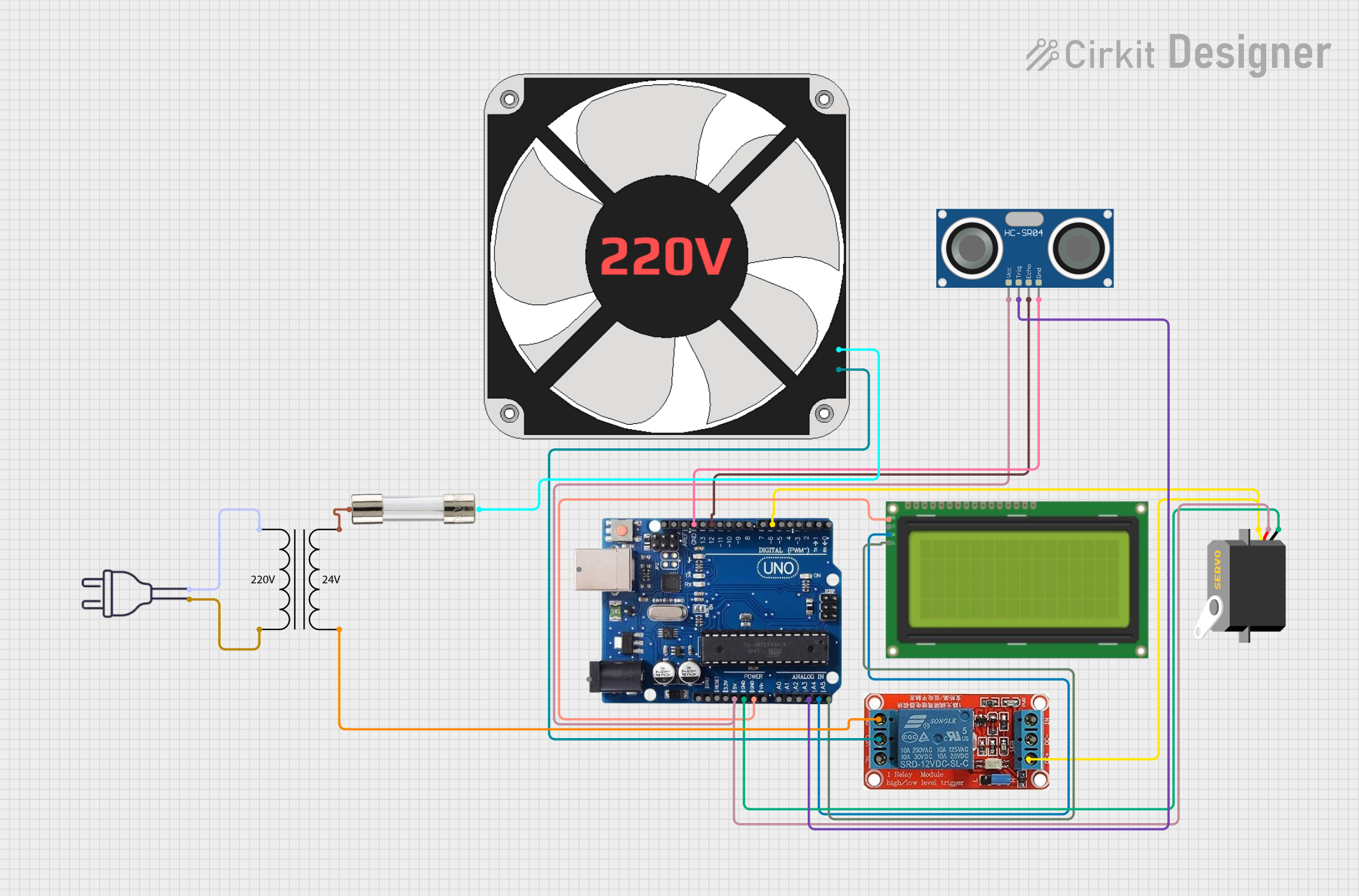
Circuit Documentation
Summary
This circuit is designed to control a fan using an Arduino Uno R3. The fan is connected to a 12V relay, which is controlled by the Arduino. Additionally, a servo motor is used to rotate the fan, and an LCD display is used to show the status of the fan. An HC-SR04 ultrasonic sensor is also included in the circuit for distance measurement.
Component List
Arduino Uno R3
- Description: Microcontroller board based on the ATmega328P.
- Pins: USB Port, Power Jack, Not Connected, IOREF, RESET, 3.3V, 5V, GND, VIN, A0, A1, A2, A3, A4/SDA, A5/SCL, SCL, SDA, AREF, 13, 12, 11, 10, 9, 8, 7, 6, 5, 4, 3, 2, 1, 0
Servo
- Description: A servo motor used for precise control of angular position.
- Pins: gnd, vcc, pulse
HC-SR04 Ultrasonic Sensor
- Description: Ultrasonic sensor for distance measurement.
- Pins: VCC, TRIG, ECHO, GND
220V Fan
- Description: A fan that operates on 220V.
- Pins: N, L
LCD 20x4 I2C
- Description: 20x4 character LCD display with I2C interface.
- Pins: GND, 5v, SCA, SCL
Power Transformer (220V to 24V)
- Description: Transformer to step down 220V AC to 24V AC.
- Pins: 2 - Primary, 1 - Primary, 3 - Secondary, 4 - Secondary
12V Relay
- Description: Relay module to control high voltage devices.
- Pins: NO, COM, NC, IN, DC-, DC+
Fuse
- Description: Electrical fuse for circuit protection.
- Pins: Terminal 1, Terminal 2
Power 220V
- Description: 220V power supply.
- Pins: hot wire, neutral wire
Wiring Details
Arduino Uno R3
- 5V connected to VCC of HC-SR04 Ultrasonic Sensor and vcc of Servo.
- GND connected to gnd of Servo, GND of LCD 20x4 I2C, and GND of HC-SR04 Ultrasonic Sensor.
- A3 connected to TRIG of HC-SR04 Ultrasonic Sensor.
- A4/SDA connected to SCA of LCD 20x4 I2C.
- A5/SCL connected to SCL of LCD 20x4 I2C.
- 12 connected to ECHO of HC-SR04 Ultrasonic Sensor.
- 6 connected to DC+ of 12V Relay and pulse of Servo.
Servo
- gnd connected to GND of Arduino Uno R3.
- vcc connected to 5V of Arduino Uno R3.
- pulse connected to 6 of Arduino Uno R3.
HC-SR04 Ultrasonic Sensor
- VCC connected to 5V of Arduino Uno R3.
- TRIG connected to A3 of Arduino Uno R3.
- ECHO connected to 12 of Arduino Uno R3.
- GND connected to GND of Arduino Uno R3.
220V Fan
- N connected to COM of 12V Relay.
- L connected to Terminal 2 of Fuse.
LCD 20x4 I2C
- GND connected to GND of Arduino Uno R3.
- 5v connected to 5V of Arduino Uno R3.
- SCA connected to A4/SDA of Arduino Uno R3.
- SCL connected to A5/SCL of Arduino Uno R3.
Power Transformer (220V to 24V)
- 2 - Primary connected to hot wire of Power 220V.
- 1 - Primary connected to neutral wire of Power 220V.
- 3 - Secondary connected to Terminal 1 of Fuse.
- 4 - Secondary connected to NO of 12V Relay.
12V Relay
- NO connected to 4 - Secondary of Power Transformer.
- COM connected to N of 220V Fan.
- DC+ connected to 6 of Arduino Uno R3.
- DC- connected to GND of Arduino Uno R3.
Fuse
- Terminal 1 connected to 3 - Secondary of Power Transformer.
- Terminal 2 connected to L of 220V Fan.
Power 220V
- hot wire connected to 2 - Primary of Power Transformer.
- neutral wire connected to 1 - Primary of Power Transformer.
Code Documentation
/*
 * This Arduino Sketch controls a servo motor to rotate a fan for 5 minutes.
 * The fan is connected to a 12V relay, which is controlled by the Arduino.
 * The servo motor is connected to pin 6 of the Arduino.
 * The relay is connected to the fan and the power transformer.
 * The LCD displays the status of the fan.
 */

#include <Servo.h>
#include <Wire.h>
#include <LiquidCrystal_I2C.h>

Servo myServo;
LiquidCrystal_I2C lcd(0x27, 20, 4);

const int relayPin = 6;
const int fanDuration = 5 * 60 * 1000; // 5 minutes in milliseconds

void setup() {
  // Initialize the servo
  myServo.attach(6);
  myServo.write(0); // Start from the right side

  // Initialize the relay pin
  pinMode(relayPin, OUTPUT);
  digitalWrite(relayPin, LOW); // Ensure relay is off

  // Initialize the LCD
  lcd.begin(20, 4); // Provide the number of columns and rows
  lcd.backlight();
  lcd.setCursor(0, 0);
  lcd.print("Fan Control System");
  lcd.setCursor(0, 1);
  lcd.print("Fan will run for 5 min");

  // Wait for 2 seconds before starting
  delay(2000);

  // Start the fan
  digitalWrite(relayPin, HIGH);
  myServo.write(90); // Rotate to the center position
  lcd.setCursor(0, 2);
  lcd.print("Fan is running...");

  // Run the fan for the specified duration
  delay(fanDuration);

  // Stop the fan
  digitalWrite(relayPin, LOW);
  myServo.write(0); // Return to the right side
  lcd.setCursor(0, 3);
  lcd.print("Fan stopped.");
}

void loop() {
  // Nothing to do here
}
This code initializes the servo motor, relay, and LCD display. It then starts the fan by activating the relay and rotating the servo motor to the center position. The LCD displays the status of the fan. After running the fan for 5 minutes, the relay is deactivated, and the servo motor returns to its initial position. The loop function is empty as there is no need for continuous execution.