Cirkit Designer
Your all-in-one circuit design IDE
Home /
Project Documentation
Arduino Nano-Based Remote-Controlled Relay System for LED, Light, and Motor
Circuit Documentation
Summary
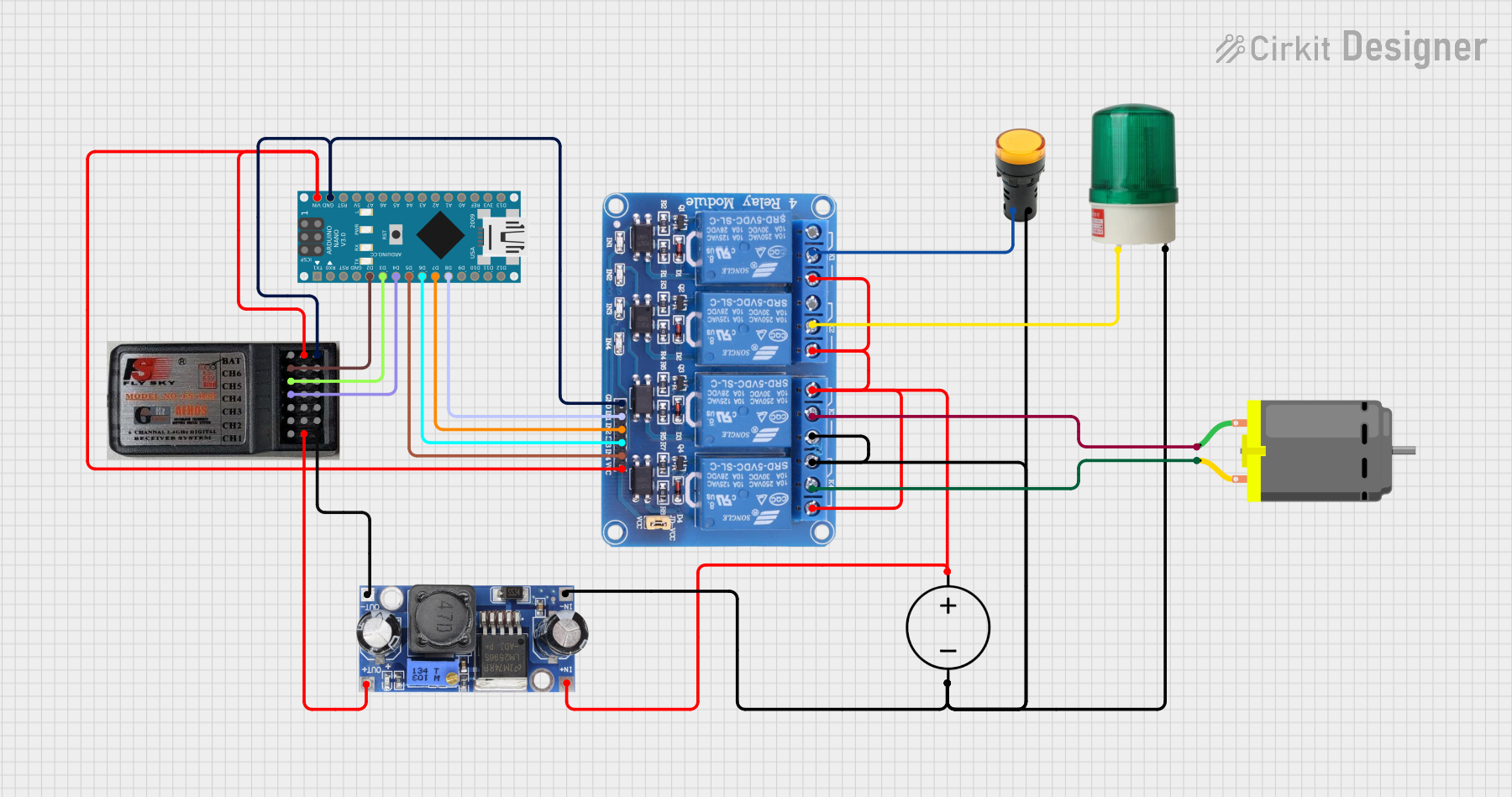
This circuit is designed to control a 4-channel relay module using an Arduino Nano and a FlySky receiver. The receiver channels CH4, CH5, and CH6 are used to control the relays connected to pins D5, D6, D7, and D8 of the Arduino Nano. CH4 controls a yellow LED, CH5 controls a green light, and CH6 controls a DC motor in forward and backward directions. The circuit also includes a DC power source and a DC-DC converter to manage power distribution.
Component List
Arduino Nano
- Description: A small, complete, and breadboard-friendly board based on the ATmega328P.
- Pins: D1/TX, D0/RX, RESET, GND, D2, D3, D4, D5, D6, D7, D8, D9, D10, D11/MOSI, D12/MISO, VIN, 5V, A7, A6, A5, A4, A3, A2, A1, A0, AREF, 3V3, D13/SCK
Relay 4 Channel 5v
- Description: A relay module that allows control of high voltage devices with low voltage signals.
- Pins: GND, IN1, IN2, IN3, IN4, VCC, COM1, COM2, COM3, COM4, NO1, NO2, NO3, NO4, NC1, NC2, NC3, NC4
DC Power Source
- Description: Provides the necessary power for the circuit.
- Pins: Ground, Positive
DC Motor
- Description: A motor that runs on direct current (DC) electricity.
- Pins: pin 1, pin 2
RC Receiver 6 Channels
- Description: A receiver for remote control signals, typically used in RC vehicles.
- Pins: CH1, VCC, GND, CH2, CH3, CH4, CH5, CH6, Bind
Green Light 220VAC
- Description: A green indicator light that operates on 220V AC.
- Pins: +, -
Pilot LED Yellow
- Description: A yellow indicator LED.
- Pins: G, +
DC-DC Converter
- Description: Converts DC voltage from one level to another.
- Pins: +VCC IN, GND IN, +VCC OUT, GND OUT
Wiring Details
Arduino Nano
- D2 connected to RC Receiver 6 Channels CH6
- D3 connected to RC Receiver 6 Channels CH5
- D4 connected to RC Receiver 6 Channels CH4
- D5 connected to Relay 4 Channel 5v IN4
- D6 connected to Relay 4 Channel 5v IN3
- D7 connected to Relay 4 Channel 5v IN2
- D8 connected to Relay 4 Channel 5v IN1
- VIN connected to RC Receiver 6 Channels VCC and Relay 4 Channel 5v VCC
- GND connected to RC Receiver 6 Channels GND and Relay 4 Channel 5v GND
Relay 4 Channel 5v
- IN1 connected to Arduino Nano D8
- IN2 connected to Arduino Nano D7
- IN3 connected to Arduino Nano D6
- IN4 connected to Arduino Nano D5
- VCC connected to Arduino Nano VIN and RC Receiver 6 Channels VCC
- GND connected to Arduino Nano GND and RC Receiver 6 Channels GND
- COM1 connected to Pilot LED Yellow G
- COM2 connected to Green Light 220VAC +
- COM3 connected to DC Motor pin 1
- COM4 connected to DC Motor pin 2
- NO1 connected to DC-DC Converter +VCC IN
- NO2 connected to DC-DC Converter +VCC IN
- NO3 connected to DC-DC Converter GND IN
- NO4 connected to DC-DC Converter +VCC IN
- NC3 connected to DC-DC Converter +VCC IN
- NC4 connected to DC-DC Converter GND IN
DC Power Source
- Positive connected to DC-DC Converter +VCC IN
- Ground connected to DC-DC Converter GND IN
DC Motor
- pin 1 connected to Relay 4 Channel 5v COM3
- pin 2 connected to Relay 4 Channel 5v COM4
RC Receiver 6 Channels
- CH6 connected to Arduino Nano D2
- CH5 connected to Arduino Nano D3
- CH4 connected to Arduino Nano D4
- VCC connected to Arduino Nano VIN and Relay 4 Channel 5v VCC
- GND connected to Arduino Nano GND and Relay 4 Channel 5v GND
Green Light 220VAC
- + connected to Relay 4 Channel 5v COM2
- - connected to DC-DC Converter GND IN
Pilot LED Yellow
- G connected to Relay 4 Channel 5v COM1
- + connected to DC-DC Converter GND IN
DC-DC Converter
- +VCC IN connected to DC Power Source Positive
- GND IN connected to DC Power Source Ground
- +VCC OUT connected to RC Receiver 6 Channels VCC
- GND OUT connected to RC Receiver 6 Channels GND
Code Documentation
/*
 * This Arduino Sketch controls a 4-channel relay module using an Arduino Nano
 * and a FlySky receiver. The receiver channels CH4, CH5, and CH6 are used to
 * control the relays connected to pins D5, D6, D7, and D8 of the Arduino Nano.
 * CH4 controls a yellow LED, CH5 controls a green light, and CH6 controls a
 * DC motor in forward and backward directions.
 */

// Pin definitions
const int relay1Pin = 5; // Relay 1 connected to D5 (Yellow LED)
const int relay2Pin = 6; // Relay 2 connected to D6 (Green Light)
const int relay3Pin = 7; // Relay 3 connected to D7 (DC Motor)
const int relay4Pin = 8; // Relay 4 connected to D8 (DC Motor)

// Receiver channel pins
const int ch4Pin = 4; // CH4 connected to D4
const int ch5Pin = 3; // CH5 connected to D3
const int ch6Pin = 2; // CH6 connected to D2

void setup() {
  // Initialize relay pins as outputs
  pinMode(relay1Pin, OUTPUT);
  pinMode(relay2Pin, OUTPUT);
  pinMode(relay3Pin, OUTPUT);
  pinMode(relay4Pin, OUTPUT);

  // Initialize receiver channel pins as inputs
  pinMode(ch4Pin, INPUT);
  pinMode(ch5Pin, INPUT);
  pinMode(ch6Pin, INPUT);
}

void loop() {
  // Read receiver channel values
  int ch4Value = pulseIn(ch4Pin, HIGH);
  int ch5Value = pulseIn(ch5Pin, HIGH);
  int ch6Value = pulseIn(ch6Pin, HIGH);

  // Control yellow LED based on CH4 input
  if (ch4Value > 1500) {
    digitalWrite(relay1Pin, HIGH); // Turn on yellow LED
  } else {
    digitalWrite(relay1Pin, LOW); // Turn off yellow LED
  }

  // Control green light based on CH5 input
  if (ch5Value > 1500) {
    digitalWrite(relay2Pin, HIGH); // Turn on green light
  } else {
    digitalWrite(relay2Pin, LOW); // Turn off green light
  }

  // Control motor direction based on CH6 input
  if (ch6Value > 1500) {
    // Forward direction
    digitalWrite(relay3Pin, HIGH);
    digitalWrite(relay4Pin, LOW);
  } else if (ch6Value < 1500) {
    // Backward direction
    digitalWrite(relay3Pin, LOW);
    digitalWrite(relay4Pin, HIGH);
  } else {
    // Stop motor
    digitalWrite(relay3Pin, LOW);
    digitalWrite(relay4Pin, LOW);
  }
}
This code initializes the relay pins as outputs and the receiver channel pins as inputs. It reads the values from the receiver channels and controls the relays accordingly to turn on/off the yellow LED, green light, and control the direction of the DC motor.