
Arduino Mega 2560 Environmental Monitoring System with Wi-Fi Connectivity
View and Edit Project In Cirkit Designer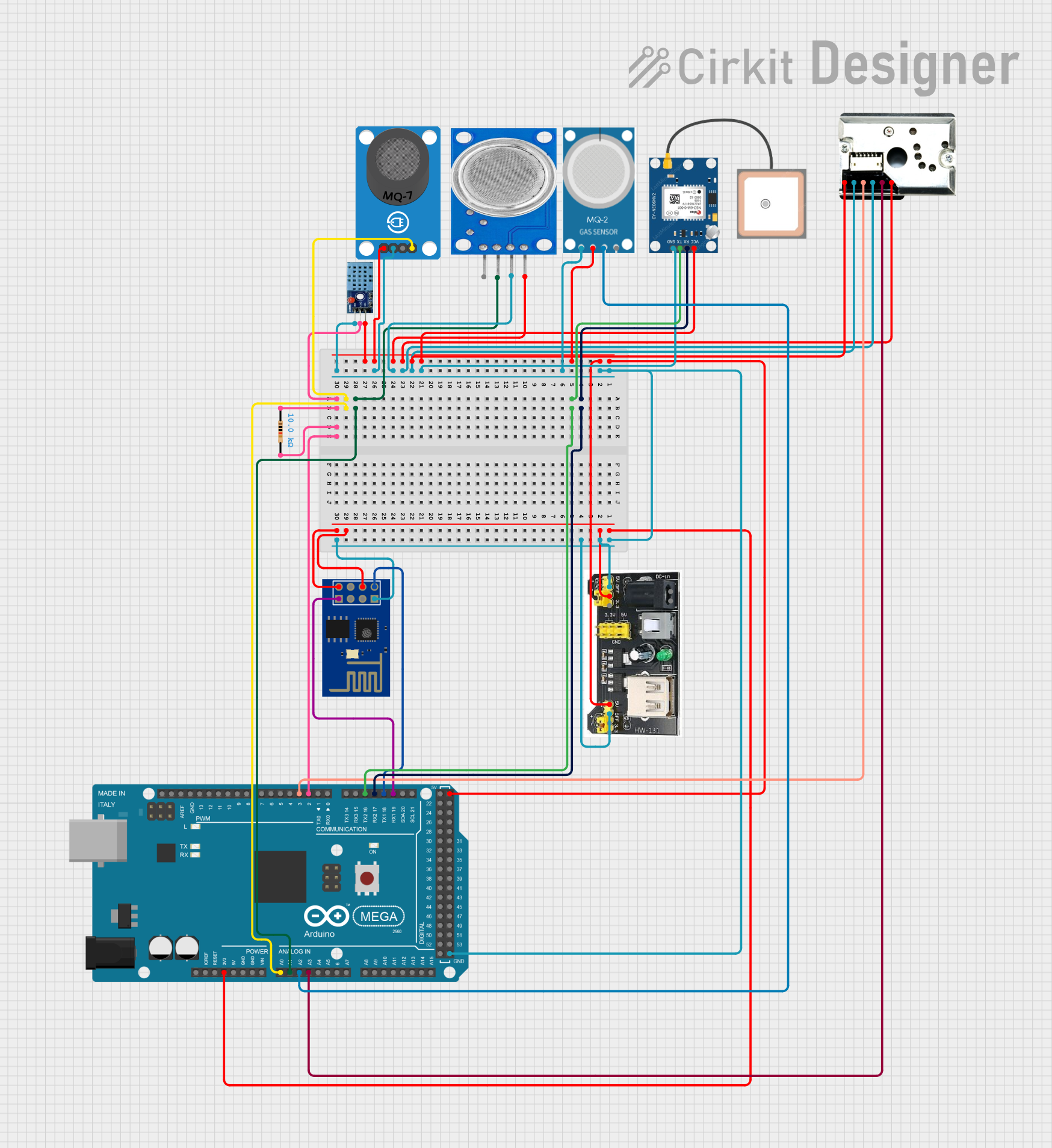
Circuit Documentation
Summary
This document provides a detailed overview of a circuit designed using an Arduino Mega 2560 microcontroller. The circuit includes various sensors and modules such as the DHT 11 temperature and humidity sensor, MQ series gas sensors, an ESP8266 WiFi module, a GPS module, and a dust sensor. The document includes a component list, wiring details, and the embedded code used in the microcontroller.
Component List
Arduino Mega 2560
- Description: A microcontroller board based on the ATmega2560.
- Pins: IOREF, RESET, 3V3, 5V, GND, VIN, A0-A15, D0-D53, AREF, SDA, SCL
DHT 11
- Description: Temperature and humidity sensor.
- Pins: VCC, GND, DATA
Resistor
- Description: A 10k Ohm resistor.
- Pins: pin1, pin2
- Properties: Resistance: 10000 Ohms
ESP8266 ESP-01 WiFi Module
- Description: WiFi module for wireless communication.
- Pins: TXD, CH_PD, RST, VCC, GND, GPIO_2, GPIO_0, RXD
MQ-7 Breakout
- Description: Carbon monoxide gas sensor.
- Pins: VCC, GND, DO, AO
MQ-2
- Description: Gas sensor for detecting LPG, i-butane, propane, methane, alcohol, hydrogen, and smoke.
- Pins: GND, VCC, ANALOG, Digital
MQ135
- Description: Air quality sensor for detecting NH3, NOx, alcohol, benzene, smoke, and CO2.
- Pins: VCC, GND, A0, D0
GP2Y1010AU0F
- Description: Optical dust sensor.
- Pins: VCC, Vout, S-GND, LED, LED-GND, V-LED
HW-131
- Description: Power supply module.
- Pins: 5V, GND, 3.3V, 5-12V
GPS NEO 6M
- Description: GPS module for location tracking.
- Pins: VCC, RX, TX, GND
Wiring Details
Arduino Mega 2560
- 3V3: Connected to HW-131 (3.3V), ESP8266 ESP-01 WiFi Module (CH_PD, VCC)
- A0: Connected to MQ-7 Breakout (AO)
- A1: Connected to MQ135 (A0)
- A2: Connected to MQ-2 (ANALOG)
- A3: Connected to GP2Y1010AU0F (Vout)
- D19/RX1: Connected to ESP8266 ESP-01 WiFi Module (RXD)
- D18/TX1: Connected to ESP8266 ESP-01 WiFi Module (TXD)
- D17 PWM/RX2: Connected to GPS NEO 6M (RX)
- D16 PWM/TX2: Connected to GPS NEO 6M (TX)
- D2 PWM: Connected to DHT 11 (DATA), Resistor (pin1), Resistor (pin2)
- D3 PWM: Connected to GP2Y1010AU0F (LED)
- GND: Connected to DHT 11 (GND), MQ-2 (GND), GPS NEO 6M (GND), GP2Y1010AU0F (LED-GND, S-GND), MQ135 (GND), MQ-7 Breakout (GND), HW-131 (GND), ESP8266 ESP-01 WiFi Module (GND)
- 5V: Connected to DHT 11 (VCC), HW-131 (5V), MQ-2 (VCC), GPS NEO 6M (VCC), GP2Y1010AU0F (V-LED, VCC), MQ135 (VCC), MQ-7 Breakout (VCC)
DHT 11
- VCC: Connected to Arduino Mega 2560 (5V)
- GND: Connected to Arduino Mega 2560 (GND)
- DATA: Connected to Arduino Mega 2560 (D2 PWM)
Resistor
- pin1: Connected to Arduino Mega 2560 (D2 PWM)
- pin2: Connected to Arduino Mega 2560 (D2 PWM)
ESP8266 ESP-01 WiFi Module
- TXD: Connected to Arduino Mega 2560 (D18/TX1)
- CH_PD: Connected to Arduino Mega 2560 (3V3)
- VCC: Connected to Arduino Mega 2560 (3V3)
- GND: Connected to Arduino Mega 2560 (GND)
- RXD: Connected to Arduino Mega 2560 (D19/RX1)
MQ-7 Breakout
- VCC: Connected to Arduino Mega 2560 (5V)
- GND: Connected to Arduino Mega 2560 (GND)
- AO: Connected to Arduino Mega 2560 (A0)
MQ-2
- GND: Connected to Arduino Mega 2560 (GND)
- VCC: Connected to Arduino Mega 2560 (5V)
- ANALOG: Connected to Arduino Mega 2560 (A2)
MQ135
- VCC: Connected to Arduino Mega 2560 (5V)
- GND: Connected to Arduino Mega 2560 (GND)
- A0: Connected to Arduino Mega 2560 (A1)
GP2Y1010AU0F
- VCC: Connected to Arduino Mega 2560 (5V)
- Vout: Connected to Arduino Mega 2560 (A3)
- S-GND: Connected to Arduino Mega 2560 (GND)
- LED: Connected to Arduino Mega 2560 (D3 PWM)
- LED-GND: Connected to Arduino Mega 2560 (GND)
- V-LED: Connected to Arduino Mega 2560 (5V)
HW-131
- 5V: Connected to Arduino Mega 2560 (5V)
- GND: Connected to Arduino Mega 2560 (GND)
- 3.3V: Connected to Arduino Mega 2560 (3V3)
GPS NEO 6M
- VCC: Connected to Arduino Mega 2560 (5V)
- RX: Connected to Arduino Mega 2560 (D17 PWM/RX2)
- TX: Connected to Arduino Mega 2560 (D16 PWM/TX2)
- GND: Connected to Arduino Mega 2560 (GND)
Code Documentation
Arduino Mega 2560 Code
void setup() {
  // put your setup code here, to run once:

}

void loop() {
  // put your main code here, to run repeatedly:

}
This code is a basic template for the Arduino Mega 2560. The setup() function is used to initialize any settings or configurations, and the loop() function contains the main code that runs repeatedly.