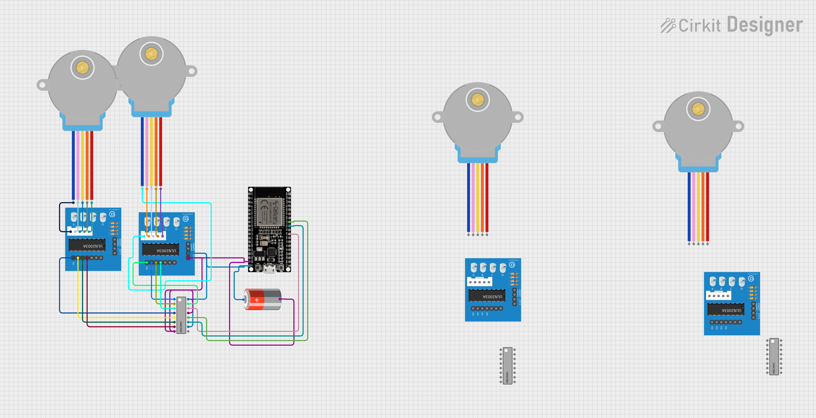
ESP32-Controlled Stepper Motor with ULN2003A Driver and 74HC595 Shift Register

Circuit Documentation
Summary of the Circuit
This circuit is designed to control a stepper motor using an ESP32 microcontroller. The stepper motor is driven by a ULN2003A driver board, which is in turn controlled via a 74HC595 shift register. The circuit allows the motor to move forward and backward with 2048 steps per revolution at a speed of 5 steps per second. The ESP32 microcontroller communicates with the shift register to set the direction and steps for the motor, and it is powered by a 5V battery.
Component List
ESP32 38 PINS
- Description: A microcontroller with WiFi and Bluetooth capabilities and a wide range of GPIO pins.
- Pins: GND, G23, G22, TXD, RXD, G21, G19, G18, G5, G17, G16, G4, G0, G2, G15, SDI, SD0, CLK, 3V3, EN, SP, SN, G34, G35, G32, 33, G25, G26, G27, G14, G12, G13, SD2, SD3, 5V
ULN2003A Breakout Board
- Description: A breakout board for the ULN2003A, a 7-channel Darlington array used to drive high-current loads.
- Pins: In 1, In 2, In 3, In 4, In 5, In 6, In 7, 0V, +5V, ON/OFF jumper switch, BLUE wire, PINK wire, YELLOW wire, ORANGE wire, RED wire
28BYJ-48 Stepper Motor
- Description: A small, 5-wire, unipolar stepper motor.
- Pins: BLUE, PINK, YELLOW, ORANGE, RED
5V Battery
- Description: A power source for the circuit.
- Pins: +, -
74HC595
- Description: An 8-bit shift register with output latches, providing serial-to-parallel conversion.
- Pins: Q1, Q2, Q3, Q4, Q5, Q6, Q7, GND, VCC, Q0, DS (DATA), OE (Enable), ST_CP (RCLK), SH_CP (SRCLK), MR (SRCLR), Q7' (QH)
Wiring Details
ESP32 38 PINS
- G19 connected to 74HC595 ST_CP (RCLK)
- G18 connected to 74HC595 SH_CP (SRCLK)
- G17 connected to 74HC595 DS (DATA)
- GND connected to common ground
- 5V connected to common 5V power rail
ULN2003A Breakout Board
- In 1 to In 4 connected to 74HC595 Q0 to Q3 respectively
- 0V connected to common ground
- +5V connected to common 5V power rail
- BLUE wire, PINK wire, YELLOW wire, ORANGE wire, RED wire connected to corresponding wires of 28BYJ-48 Stepper Motor
28BYJ-48 Stepper Motor
- BLUE, PINK, YELLOW, ORANGE, RED wires connected to corresponding wires on ULN2003A Breakout Board
5V Battery
- connected to common 5V power rail
- connected to common ground
74HC595
- ST_CP (RCLK) connected to ESP32 G19
- SH_CP (SRCLK) connected to ESP32 G18
- DS (DATA) connected to ESP32 G17
- OE (Enable) connected to GND
- MR (SRCLR) connected to VCC
- VCC connected to common 5V power rail
- GND connected to common ground
- Q0 to Q3 connected to ULN2003A In 1 to In 4 respectively
Documented Code
/*
 * This Arduino sketch controls a stepper motor using an ESP32 microcontroller.
 * The stepper motor is driven by a ULN2003A driver board, which is controlled
 * via a 74HC595 shift register. The motor will move forward and backward with
 * 2048 steps per revolution and a speed of 5 steps per second.
 */

#include <Stepper.h>

// Define the control pins for the stepper motor
#define DATA_PIN 12
#define LATCH_PIN 14
#define CLOCK_PIN 27

// Number of steps per revolution
const int stepsPerRevolution = 2048;

// Initialize the Stepper library
Stepper stepper(stepsPerRevolution, DATA_PIN, CLOCK_PIN, LATCH_PIN);

void setup() {
  Serial.begin(115200); // Initialize serial communication
  stepper.setSpeed(5); // Set the speed to 5 steps per second
}

void loop() {
  if (Serial.available() > 0) {
    String command = Serial.readStringUntil('\n');
    processCommand(command);
  }
}

void processCommand(String command) {
  command.trim();
  if (command.startsWith("F")) {
    int steps = command.substring(1).toInt();
    moveMotor(steps);
  } else if (command.startsWith("B")) {
    int steps = command.substring(1).toInt();
    moveMotor(-steps);
  }
}

void moveMotor(int steps) {
  stepper.step(steps);
}
This code is designed to be uploaded to the ESP32 microcontroller. It sets up the stepper motor with the defined number of steps per revolution and initializes the serial communication for receiving commands. The processCommand function interprets commands starting with "F" for forward or "B" for backward, followed by the number of steps to move the motor. The moveMotor function then executes the movement.