Cirkit Designer
Your all-in-one circuit design IDE
Home /
Project Documentation
Arduino UNO-Based Weather Station with LCD Display and DC Motor Control
Circuit Documentation
Summary
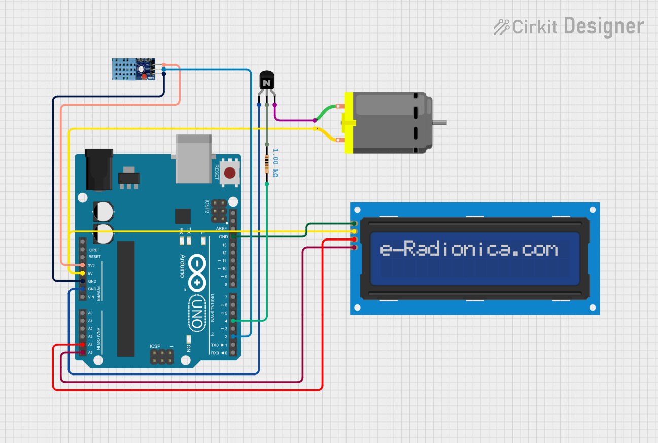
This document provides a detailed overview of a circuit that includes an Arduino UNO microcontroller, an LCD screen, a DHT11 temperature and humidity sensor, an NPN transistor, a DC motor, and a resistor. The circuit is designed to interface these components with the Arduino UNO, allowing for data display on the LCD screen and control of the DC motor.
Component List
Arduino UNO
- Description: A microcontroller board based on the ATmega328P.
- Pins: UNUSED, IOREF, Reset, 3.3V, 5V, GND, Vin, A0, A1, A2, A3, A4, A5, SCL, SDA, AREF, D13, D12, D11, D10, D9, D8, D7, D6, D5, D4, D3, D2, D1, D0
LCD screen 16x2 I2C
- Description: A 16x2 character LCD display with I2C interface.
- Pins: SCL, SDA, VCC, GND
NPN Transistor (EBC)
- Description: A standard NPN transistor with emitter, base, and collector pins.
- Pins: emitter, base, collector
DHT 11
- Description: A temperature and humidity sensor.
- Pins: VCC, GND, DATA
DC Motor
- Description: A simple DC motor.
- Pins: pin 1, pin 2
Resistor
- Description: A resistor with a resistance of 1000 Ohms.
- Pins: pin1, pin2
- Properties:
- Resistance: 1000 Ohms
Wiring Details
Arduino UNO
- 3.3V: Connected to VCC of DHT 11
- 5V: Connected to pin 2 of DC Motor and VCC of LCD screen 16x2 I2C
- GND: Connected to GND of DHT 11, emitter of NPN Transistor, GND of LCD screen 16x2 I2C
- A4: Connected to SDA of LCD screen 16x2 I2C
- A5: Connected to SCL of LCD screen 16x2 I2C
- D4: Connected to pin2 of Resistor
- D2: Connected to DATA of DHT 11
LCD screen 16x2 I2C
- SCL: Connected to A5 of Arduino UNO
- SDA: Connected to A4 of Arduino UNO
- VCC: Connected to 5V of Arduino UNO
- GND: Connected to GND of Arduino UNO
NPN Transistor (EBC)
- emitter: Connected to GND of Arduino UNO
- base: Connected to pin1 of Resistor
- collector: Connected to pin 1 of DC Motor
DHT 11
- VCC: Connected to 3.3V of Arduino UNO
- GND: Connected to GND of Arduino UNO
- DATA: Connected to D2 of Arduino UNO
DC Motor
- pin 1: Connected to collector of NPN Transistor
- pin 2: Connected to 5V of Arduino UNO
Resistor
- pin1: Connected to base of NPN Transistor
- pin2: Connected to D4 of Arduino UNO
Documented Code
Arduino UNO Code (sketch.ino)
void setup() {
  // put your setup code here, to run once:

}

void loop() {
  // put your main code here, to run repeatedly:

}
Documentation (documentation.txt)
This document provides a comprehensive overview of the circuit, including a summary, component list, wiring details, and documented code.