
Wi-Fi Controlled Distance Sensor with LED Indicator using ESP8266 and HC-SR04
View and Edit Project In Cirkit Designer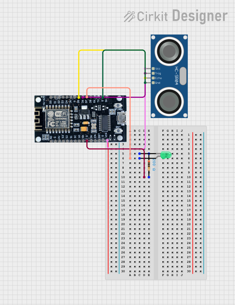
Circuit Documentation
Summary
This document provides a detailed overview of a circuit that includes an ESP8266 microcontroller, an HC-SR04 Ultrasonic Sensor, a resistor, and a green LED. The ESP8266 microcontroller is used to control the LED and read data from the ultrasonic sensor. The resistor is used to limit the current through the LED.
Component List
ESP8266
- Description: A Wi-Fi enabled microcontroller.
- Pins: 3V, G, D8, D7, D6, D5, D4, D3, D2, D1, D0, A0, S3, S2, S1, SC, S0, SK, EN, VIN, RST, VU
HC-SR04 Ultrasonic Sensor
- Description: A sensor used to measure distance by using ultrasonic waves.
- Pins: VCC, TRIG, ECHO, GND
Resistor
- Description: A 200 Ohm resistor used to limit current.
- Pins: pin1, pin2
- Properties:
- Resistance: 200 Ohms
LED: Two Pin (green)
- Description: A green LED used for visual indication.
- Pins: cathode, anode
Wiring Details
ESP8266
- D7 is connected to the anode of the green LED.
- G is connected to:
- pin2 of the resistor.
- GND of the HC-SR04 Ultrasonic Sensor.
- D6 is connected to the TRIG pin of the HC-SR04 Ultrasonic Sensor.
- D5 is connected to the ECHO pin of the HC-SR04 Ultrasonic Sensor.
- VIN is connected to the VCC pin of the HC-SR04 Ultrasonic Sensor.
HC-SR04 Ultrasonic Sensor
- VCC is connected to the VIN pin of the ESP8266.
- TRIG is connected to the D6 pin of the ESP8266.
- ECHO is connected to the D5 pin of the ESP8266.
- GND is connected to the G pin of the ESP8266.
Resistor
- pin1 is connected to the cathode of the green LED.
- pin2 is connected to the G pin of the ESP8266.
LED: Two Pin (green)
- anode is connected to the D7 pin of the ESP8266.
- cathode is connected to the pin1 of the resistor.
Code
No code is provided for this circuit.
This document provides a comprehensive overview of the circuit, including a summary, detailed component descriptions, wiring details, and code documentation.