
Arduino UNO-Based Smart Study Session Manager with PIR and Sound Sensors
View and Edit Project In Cirkit Designer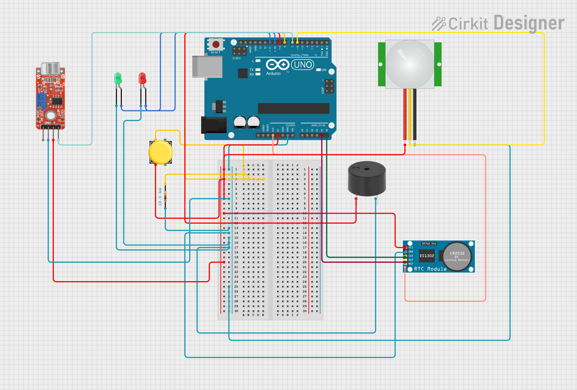
Circuit Documentation
Summary
This circuit is designed to monitor environmental conditions and user interactions using various sensors and indicators. It includes an Arduino UNO microcontroller, a Real-Time Clock (RTC), a Passive Infrared (PIR) sensor, a sound sensor, LEDs, a pushbutton, and a buzzer. The system can detect motion, sound, and button presses to trigger different actions such as starting a session, taking a break, or indicating status through LEDs and a buzzer.
Component List
Arduino UNO
- Description: Microcontroller board based on the ATmega328P.
- Pins: UNUSED, IOREF, Reset, 3.3V, 5V, GND, Vin, A0, A1, A2, A3, A4, A5, SCL, SDA, AREF, D13, D12, D11, D10, D9, D8, D7, D6, D5, D4, D3, D2, D1, D0
RTC
- Description: Real-Time Clock module for keeping track of time.
- Pins: VCC, GND, CLK, DAT, RST
PIR sensor
- Description: Passive Infrared sensor for motion detection.
- Pins: VDD, SIG, GND
LED: Two Pin (red)
- Description: Red LED for indicating break mode.
- Pins: cathode, anode
LED: Two Pin (green)
- Description: Green LED for indicating study mode.
- Pins: cathode, anode
Pushbutton
- Description: Pushbutton for user interaction.
- Pins: Pin 2, Pin 1, Pin 3, Pin 4
Resistor
- Description: 10k Ohm resistor.
- Pins: pin1, pin2
- Properties: Resistance: 10k Ohms
Buzzer
- Description: Buzzer for audio feedback.
- Pins: PIN, GND
KY-037 Microphone
- Description: Sound sensor module.
- Pins: Analog output, Ground, VCC, Digital output
Wiring Details
Arduino UNO
5V connected to:
- Pushbutton Pin 2
- PIR sensor VDD
- RTC VCC
- KY-037 Microphone VCC
GND connected to:
- KY-037 Microphone Ground
- Resistor pin1
- RTC GND
- LED (red) cathode
- LED (green) cathode
- Buzzer GND
- PIR sensor GND
3.3V connected to:
- RTC RST
A4 connected to:
- RTC DAT
A5 connected to:
- RTC CLK
D6 connected to:
- PIR sensor SIG
D7 connected to:
- KY-037 Microphone Digital output
D8 connected to:
- Pushbutton Pin 1
- Resistor pin2
D9 connected to:
- Buzzer PIN
D10 connected to:
- LED (green) anode
D11 connected to:
- LED (red) anode
RTC
VCC connected to:
- Arduino UNO 5V
GND connected to:
- Arduino UNO GND
CLK connected to:
- Arduino UNO A5
DAT connected to:
- Arduino UNO A4
RST connected to:
- Arduino UNO 3.3V
PIR sensor
VDD connected to:
- Arduino UNO 5V
SIG connected to:
- Arduino UNO D6
GND connected to:
- Arduino UNO GND
LED: Two Pin (red)
cathode connected to:
- Arduino UNO GND
anode connected to:
- Arduino UNO D11
LED: Two Pin (green)
cathode connected to:
- Arduino UNO GND
anode connected to:
- Arduino UNO D10
Pushbutton
Pin 1 connected to:
- Arduino UNO D8
- Resistor pin2
Pin 2 connected to:
- Arduino UNO 5V
Resistor
pin1 connected to:
- Arduino UNO GND
pin2 connected to:
- Arduino UNO D8
- Pushbutton Pin 1
Buzzer
PIN connected to:
- Arduino UNO D9
GND connected to:
- Arduino UNO GND
KY-037 Microphone
VCC connected to:
- Arduino UNO 5V
Ground connected to:
- Arduino UNO GND
Digital output connected to:
- Arduino UNO D7
Code Documentation
// Pin assignments
const int soundPin = 7;    // Pin connected to the sound sensor digital output (DO)
const int buzzerPin = 9;   // Pin connected to the buzzer
const int greenLED = 10;   // Pin connected to the green LED (study mode)
const int redLED = 11;     // Pin connected to the red LED (break mode)
const int buttonPin = 8;   // Pin connected to the push button
const int pirPin = 6;      // Pin connected to the PIR sensor

// Variable to hold the push button state
int buttonState = 0;
int pirState = 0; // Variable to hold PIR sensor state

void setup() {
  // Initialize serial communication
  Serial.begin(9600);

  // Set pins as input or output
  pinMode(soundPin, INPUT);   // Set sound sensor pin as input
  pinMode(buzzerPin, OUTPUT); // Set buzzer pin as output
  pinMode(greenLED, OUTPUT);  // Set green LED pin as output
  pinMode(redLED, OUTPUT);    // Set red LED pin as output
  pinMode(buttonPin, INPUT);  // Set push button pin as input
  pinMode(pirPin, INPUT);     // Set PIR sensor pin as input

  // Initialize the LEDs to OFF
  digitalWrite(greenLED, LOW);
  digitalWrite(redLED, LOW);
}

void loop() {
  // Read the state of the push button
  buttonState = digitalRead(buttonPin);

  // Read the state of the PIR sensor
  pirState = digitalRead(pirPin);

  // Check if the button is pressed (start session)
  if (buttonState == HIGH) {
    Serial.println("Button Pressed! Starting Session...");
    startSession();
  }

  // Check if motion is detected by PIR sensor (if no movement, take a break)
  if (pirState == LOW) {
    Serial.println("No motion detected. Reminder to take a stretch break.");
    takeStretchBreak();
  }

  // Check for sound detection from the sound sensor
  int soundState = digitalRead(soundPin);  // Read the sound sensor input
  if (soundState == HIGH) {
    Serial.println("Sound Detected! Triggering action...");
    soundDetectedAction();
  }

  delay(200); // Small delay to prevent bouncing effects or rapid toggling
}

void startSession() {
  // Turn on the green LED (study mode) and turn off the red LED
  digitalWrite(greenLED, HIGH);
  digitalWrite(redLED, LOW);

  // Sound the buzzer to indicate session start
  tone(buzzerPin, 1000, 500);  // Play sound for 500ms
}

void takeStretchBreak() {
  // Turn off the green LED (study mode) and turn on the red LED (break mode)
  digitalWrite(greenLED, LOW);
  digitalWrite(redLED, HIGH);

  // Sound the buzzer to indicate it's time for a break
  tone(buzzerPin, 500, 500);  // Play break sound for 500ms
}

void soundDetectedAction() {
  // If sound is detected, take appropriate action (e.g., start session)
  // You can modify this to perform different actions based on the sound
  startSession();
}
This code initializes the pins for the sensors and actuators, reads their states, and performs actions based on the inputs. The main loop continuously checks the state of the push button, PIR sensor, and sound sensor to trigger the appropriate actions.