
ESP32-Controlled Multi-MPU6050 and MPU9250 IMU Data Aggregator
View and Edit Project In Cirkit Designer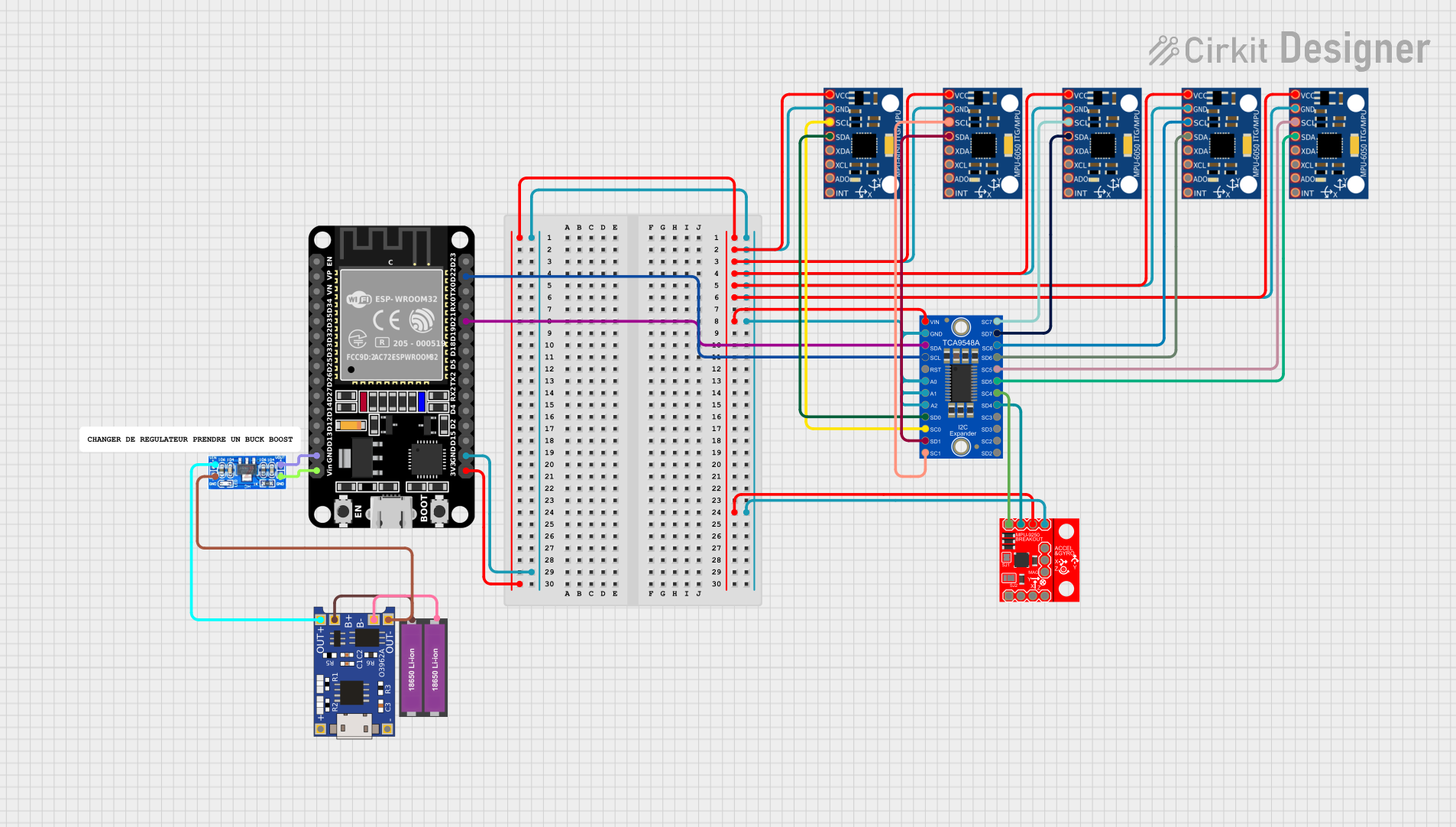
Circuit Documentation
Summary
The circuit in question is designed to interface multiple MPU-6050 sensors and a SparkFun IMU Breakout - MPU-9250 sensor with an ESP32 microcontroller through an Adafruit TCA9548A I2C multiplexer. The ESP32 serves as the central processing unit, collecting data from the sensors and performing computations to determine angles based on accelerometer and gyroscope readings. The circuit is powered by a pair of 18650 Li-ion batteries, regulated by a TP4056 charging module and an AMS1117 voltage regulator to ensure stable power delivery to the components.
Component List
Microcontroller
- ESP32 (30 pin): A powerful microcontroller with Wi-Fi and Bluetooth capabilities, featuring a variety of digital and analog I/O pins.
Sensors
- MPU-6050: A 6-axis motion tracking device that combines a 3-axis gyroscope and a 3-axis accelerometer.
- SparkFun IMU Breakout - MPU-9250: A 9-axis motion tracking device with a gyroscope, accelerometer, and magnetometer.
Multiplexer
- Adafruit TCA9548A: An I2C multiplexer that allows multiple I2C devices with the same address to be connected to a single microcontroller.
Power Management
- TP4056: A lithium battery charging module with battery protection.
- AMS1117: A voltage regulator that provides a stable output voltage.
- 18650 Li-ion Battery x 2: A pair of rechargeable batteries providing the power source for the circuit.
Miscellaneous
- Comment: A placeholder for additional notes or comments about the circuit.
Wiring Details
ESP32 (30 pin)
3V3connected to VCC of all MPU-6050 sensors, Adafruit TCA9548A, and SparkFun IMU Breakout - MPU-9250.GNDconnected to GND of all components and to theVolt Outof AMS1117.Vinconnected toGNDof AMS1117.D22(SCL) connected toINPUTSCLof Adafruit TCA9548A.D21(SDA) connected toINPUTSDAof Adafruit TCA9548A.
MPU-6050
VCCandGNDconnected as described above.SCLandSDAconnected to corresponding SCL and SDA pins on Adafruit TCA9548A channels.
SparkFun IMU Breakout - MPU-9250
VDDandGNDconnected as described above.SCL/SCLKandSDA/SDIconnected to4SCLand4SDAon Adafruit TCA9548A.
Adafruit TCA9548A
VCCandGNDconnected as described above.INPUTSDAandINPUTSCLconnected to ESP32.- Channels
0SCLto7SCLand0SDAto7SDAconnected to corresponding SCL and SDA pins on MPU-6050 sensors and MPU-9250.
TP4056
OUT-connected toGNDof AMS1117.B-connected to-of 18650 Li-ion Battery x 2.B+connected to+of 18650 Li-ion Battery x 2.OUT+connected toVolt Inof AMS1117.
AMS1117
Volt Outconnected toGNDof ESP32.GNDconnected toOUT-of TP4056.Volt Inconnected toOUT+of TP4056.
Documented Code
#include <Wire.h>
#include <Adafruit_MPU6050.h>
#include <Adafruit_Sensor.h>
#include <ClosedCube_TCA9538.h>
#include <MPU9250.h>

// Create instances for the sensors and multiplexer
ClosedCube_TCA9538 tca;
Adafruit_MPU6050 mpu[5];
MPU9250 mpu9250(Wire, 0x68);

float angleX[5] = {0};
float angleY[5] = {0};
float angleZ[5] = {0};
float alpha = 0.98;

void setup() {
  Serial.begin(115200);
  Wire.begin();

  // Initialize the TCA9538
  if (!tca.begin(0x70)) { // Default I2C address for TCA9538
    Serial.println("Couldn't find TCA9538!");
    while (1);
  }

  // Initialize the MPU6050 sensors
  for (int i = 0; i < 5; i++) {
    tca.writePort(1 << i); // Select the appropriate channel
    if (!mpu[i].begin()) {
      Serial.print("Failed to find MPU6050 #");
      Serial.println(i);
      while (1);
    }
  }

  // Initialize the MPU9250 sensor
  if (mpu9250.begin() != 0) {
    Serial.println("MPU9250 connection failed!");
    while (1);
  }
}

void loop() {
  sensors_event_t a, g, temp;
  for (int i = 0; i < 5; i++) {
    tca.writePort(1 << i); // Select the appropriate channel
    mpu[i].getEvent(&a, &g, &temp);

    float accelAngleX = atan2(a.acceleration.y, a.acceleration.z) * 180 / PI;
    float accelAngleY = atan2(-a.acceleration.x, sqrt(a.acceleration.y * a.acceleration.y + a.acceleration.z * a.acceleration.z)) * 180 / PI;

    angleX[i] = alpha * (angleX[i] + g.gyro.x * 0.01) + (1 - alpha) * accelAngleX;
    angleY[i] = alpha * (angleY[i] + g.gyro.y * 0.01) + (1 - alpha) * accelAngleY;

    Serial.print("MPU6050 #");
    Serial.print(i);
    Serial.print(" Angle X: ");
    Serial.print(angleX[i]);
    Serial.print(" Angle Y: ");
    Serial.print(angleY[i]);
    Serial.println();
  }

  // Read data from MPU9250
  mpu9250.readSensor();
  float accelAngleX = atan2(mpu9250.getAccelY_mss(), mpu9250.getAccelZ_mss()) * 180 / PI;
  float accelAngleY = atan2(-mpu9250.getAccelX_mss(), sqrt(mpu9250.getAccelY_mss() * mpu9250.getAccelY_mss() + mpu9250.getAccelZ_mss() * mpu9250.getAccelZ_mss())) * 180 / PI;

  angleX[5] = alpha * (angleX[5] + mpu9250.getGyroX_rads() * 0.01) + (1 - alpha) * accelAngleX;
  angleY[5] = alpha * (angleY[5] + mpu9250.getGyroY_rads() * 0.01) + (1 - alpha) * accelAngleY;

  Serial.print("MPU9250 Angle X: ");
  Serial.print(angleX[5]);
  Serial.print(" Angle Y: ");
  Serial.print(angleY[5]);
  Serial.println();

  delay(100);
}
This code initializes and reads data from multiple MPU6050 sensors and an MPU9250 sensor using an I2C multiplexer. It calculates the angles based on accelerometer and gyroscope data and prints them to the serial monitor. The TCA9538 multiplexer is used to select the appropriate sensor before reading data. The code includes error checking to ensure that all sensors are properly initialized before entering the main loop.