ESP32-Based Voice-Controlled Automation System with Data Logging and Servo Actuation
Circuit Documentation
Summary
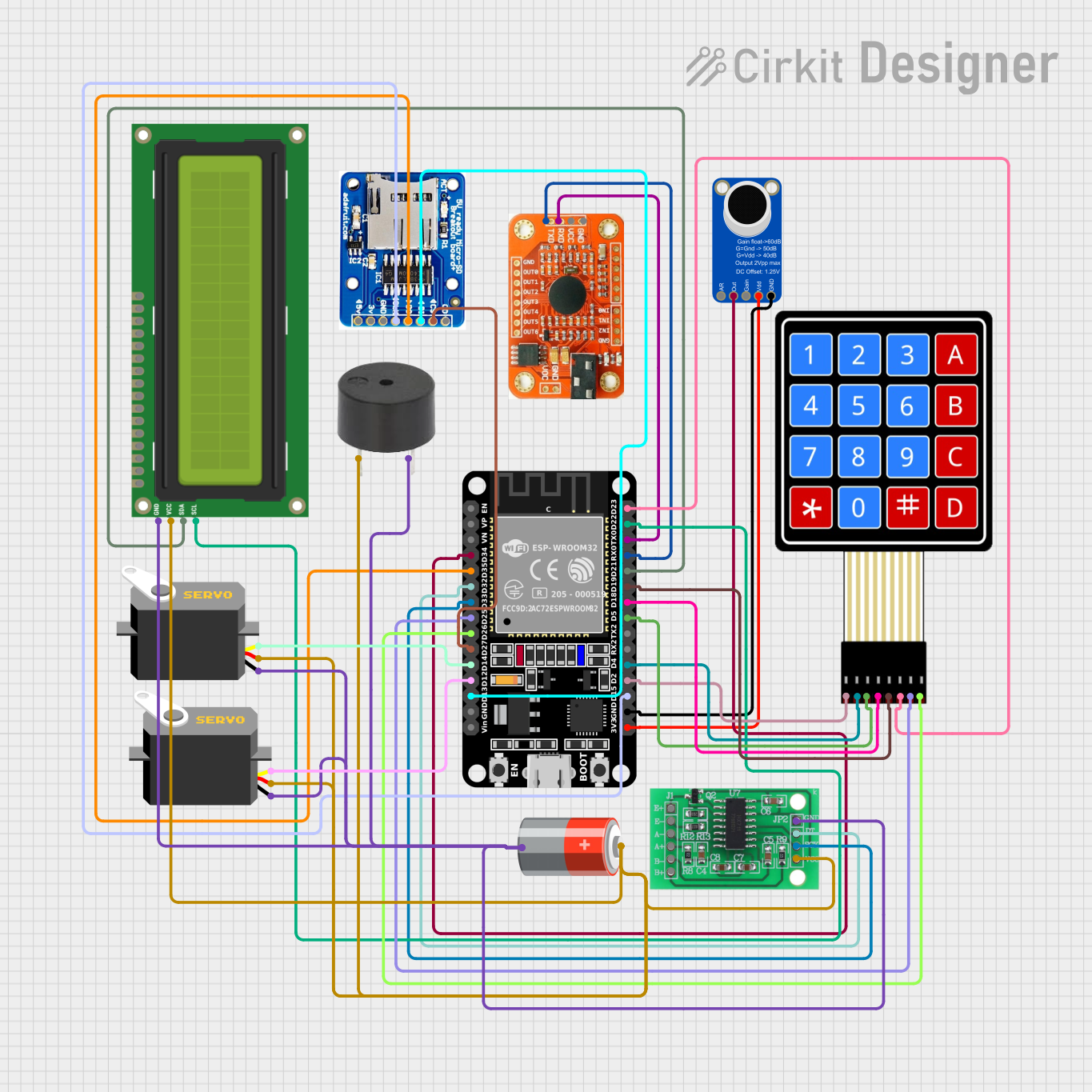
The circuit in question appears to be a multifunctional embedded system based on the ESP32 microcontroller. The ESP32 serves as the central processing unit, interfacing with various peripherals including a voice recognition module, an electret microphone amplifier, a load cell interface (HX711), an I2C LCD screen, a membrane matrix keypad, a buzzer, a microSD card socket, and two servo motors. The system is powered by a 5V battery. The ESP32's GPIO pins are used to communicate with these components, either through direct digital I/O or communication protocols such as I2C.
Component List
ESP32 (30 pin)
- A 30-pin microcontroller with Wi-Fi and Bluetooth capabilities. It is the main processing unit of the circuit.
Voice Recognition Module
- A module capable of recognizing voice commands and interfacing with the ESP32 via serial communication.
Adafruit MAX9814 Electret Microphone Amplifier
- An automatic gain control microphone amplifier used to amplify the signal from a microphone for the ESP32 to process.
HX711 - Bridge Sensor Interface
- A precision 24-bit analog-to-digital converter (ADC) designed for weigh scales and industrial control applications to interface directly with a bridge sensor.
I2C LCD 16x2 Screen
- A 16x2 character LCD display that uses the I2C communication protocol for displaying information.
4X4 Membrane Matrix Keypad
- A 16-button keypad that provides user input to the microcontroller.
Buzzer
- An electronic buzzer for audio feedback, driven by a digital signal from the ESP32.
MicroSD Card Socket
- A socket for a microSD card that allows the ESP32 to read from and write to the card.
5V Battery
- The power source for the circuit, providing 5V to the components.
Servo (x2)
- Two servo motors that can be precisely controlled by the ESP32 to move to specific angles.
Wiring Details
ESP32 (30 pin)
D34connected to Adafruit MAX9814 Electret Microphone AmplifierOUTPUTD35connected to MicroSD Card SocketDOD32connected to HX711DATA (OUT)D33connected to HX711SCK - CLOCK (IN)D25,D26,D23,D19,D18,D5,D4,D2connected to corresponding pinsC3,C4,C2,C1,R4,R3,R2,R1of the 4X4 Membrane Matrix KeypadD27connected to MicroSD Card SocketCSD14,D12connected topulsepins of the two Servo motorsD13connected to MicroSD Card SocketDID22connected to I2C LCD 16x2 ScreenSCLTX0connected to Voice Recognition ModuleRDXRX0connected to Voice Recognition ModuleRTXD21connected to I2C LCD 16x2 ScreenSDAD15connected to MicroSD Card SocketCLKGNDconnected to common ground net3V3connected to Adafruit MAX9814 Electret Microphone AmplifierVDD
Voice Recognition Module
GNDconnected to common ground netVCCconnected to common power netRDXconnected to ESP32TX0RTXconnected to ESP32RX0
Adafruit MAX9814 Electret Microphone Amplifier
GNDconnected to common ground netVDDconnected to ESP323V3OUTPUTconnected to ESP32D34
HX711 - Bridge Sensor Interface
DATA (OUT)connected to ESP32D32SCK - CLOCK (IN)connected to ESP32D33GND - GROUNDconnected to common ground net3.3/3.5V Supplyconnected to common power net
I2C LCD 16x2 Screen
SCLconnected to ESP32D22SDAconnected to ESP32D21GNDconnected to common ground netVCC (5V)connected to common power net
4X4 Membrane Matrix Keypad
R1,R2,R3,R4,C1,C2,C3,C4connected to corresponding ESP32 pinsD2,D4,D5,D18,D19,D23,D25,D26
Buzzer
PINconnected to common power netGNDconnected to common ground net
MicroSD Card Socket
DO,CS,DI,CLKconnected to corresponding ESP32 pinsD35,D27,D13,D15GNDconnected to common ground net3Vconnected to common power net (if 3.3V is required)5Vconnected to common power net (if 5V is required)
5V Battery
+connected to common power net-connected to common ground net
Servo (x2)
gndconnected to common ground netvccconnected to common power netpulseconnected to corresponding ESP32 pinsD14,D12
Documented Code
No code was provided for the microcontrollers in the circuit. The documentation of the code would typically include descriptions of the functions, the logic behind the main loop, and any interrupt service routines or handlers. It would also detail how the code interacts with each of the components, including initialization of peripherals, reading from sensors, writing to displays, and handling user input.