
Circuit Documentation
Summary
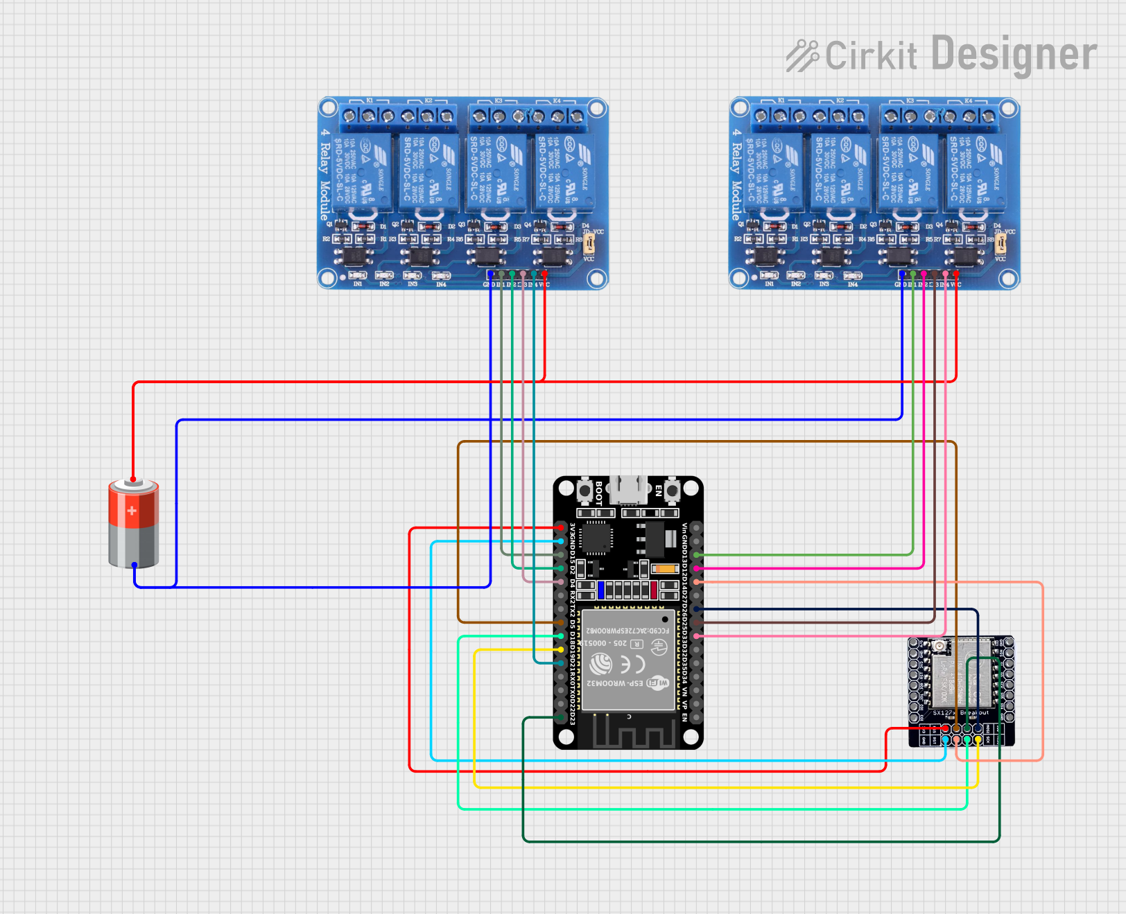
This circuit integrates an ESP32 microcontroller with a LORA_RA02 module for wireless communication and two 4-channel 5V relays for controlling external devices. The ESP32 is responsible for handling the logic and communication, while the relays enable the ESP32 to switch higher power devices on and off. A 5V battery provides power to the relays and the ESP32 through a common ground and voltage supply network.
Component List
ESP32 (30 pin)
- Description: A microcontroller with Wi-Fi and Bluetooth capabilities, featuring a variety of digital and analog pins.
- Pins: EN, VP, VN, D34, D35, D32, D33, D25, D26, D27, D14, D12, D13, GND, Vin, D23, D22, TX0, RX0, D21, D19, D18, D5, TX2, RX2, D4, D2, D15, 3V3
LORA_RA02
- Description: A wireless communication module that operates on the LoRa protocol, suitable for long-range, low-power communication.
- Pins: A/G, GND, 3V3, RST, IO_0, IO_1, IO-2, IO_3, NSS, MOSI, MISO, SCK, IO_5, IO_4
Relay 4 Channel 5v (Two Instances)
- Description: A 4-channel relay module that allows the ESP32 to control up to four high-power devices.
- Pins: GND, IN1, IN2, IN3, IN4, VCC, COM1, COM2, COM3, COM4, NO1, NO2, NO3, NO4, NC1, NC2, NC3, NC4
5v Battery
- Description: A power source for the circuit, providing 5V to the relay modules and the ESP32.
- Pins: +, -
Wiring Details
ESP32 (30 pin)
- D33 -> Relay 4 Channel 5v (IN4)
- D25 -> Relay 4 Channel 5v (IN3)
- D26 -> LORA_RA02 (IO_0)
- D14 -> LORA_RA02 (RST)
- D12 -> Relay 4 Channel 5v (IN2)
- D13 -> Relay 4 Channel 5v (IN1)
- D23 -> LORA_RA02 (MOSI)
- D21 -> Relay 4 Channel 5v (IN4)
- D19 -> LORA_RA02 (MISO)
- D18 -> LORA_RA02 (SCK)
- D5 -> LORA_RA02 (NSS)
- D4 -> Relay 4 Channel 5v (IN3)
- D2 -> Relay 4 Channel 5v (IN2)
- D15 -> Relay 4 Channel 5v (IN1)
- GND -> LORA_RA02 (GND), Relay 4 Channel 5v (GND)
- 3V3 -> LORA_RA02 (3V3)
LORA_RA02
- IO_0 -> ESP32 (D26)
- RST -> ESP32 (D14)
- MOSI -> ESP32 (D23)
- MISO -> ESP32 (D19)
- SCK -> ESP32 (D18)
- NSS -> ESP32 (D5)
- GND -> ESP32 (GND)
- 3V3 -> ESP32 (3V3)
Relay 4 Channel 5v (First Instance)
- IN1 -> ESP32 (D15)
- IN2 -> ESP32 (D2)
- IN3 -> ESP32 (D4)
- IN4 -> ESP32 (D21)
- GND -> 5v Battery (-)
- VCC -> 5v Battery (+)
Relay 4 Channel 5v (Second Instance)
- IN1 -> ESP32 (D13)
- IN2 -> ESP32 (D12)
- IN3 -> ESP32 (D25)
- IN4 -> ESP32 (D33)
- GND -> 5v Battery (-)
- VCC -> 5v Battery (+)
5v Battery
-
- -> Relay 4 Channel 5v (VCC)
-
- -> Relay 4 Channel 5v (GND), ESP32 (GND)
Documented Code
There is no code provided for the microcontroller. The code would typically initialize the ESP32's GPIO pins for communication with the LORA_RA02 module and to control the relay channels. It would also handle the logic for when to activate each relay and manage the wireless communication via LoRa.