
Arduino UNO Automated Tank Flush System with LCD Display and Motor Control
View and Edit Project In Cirkit Designer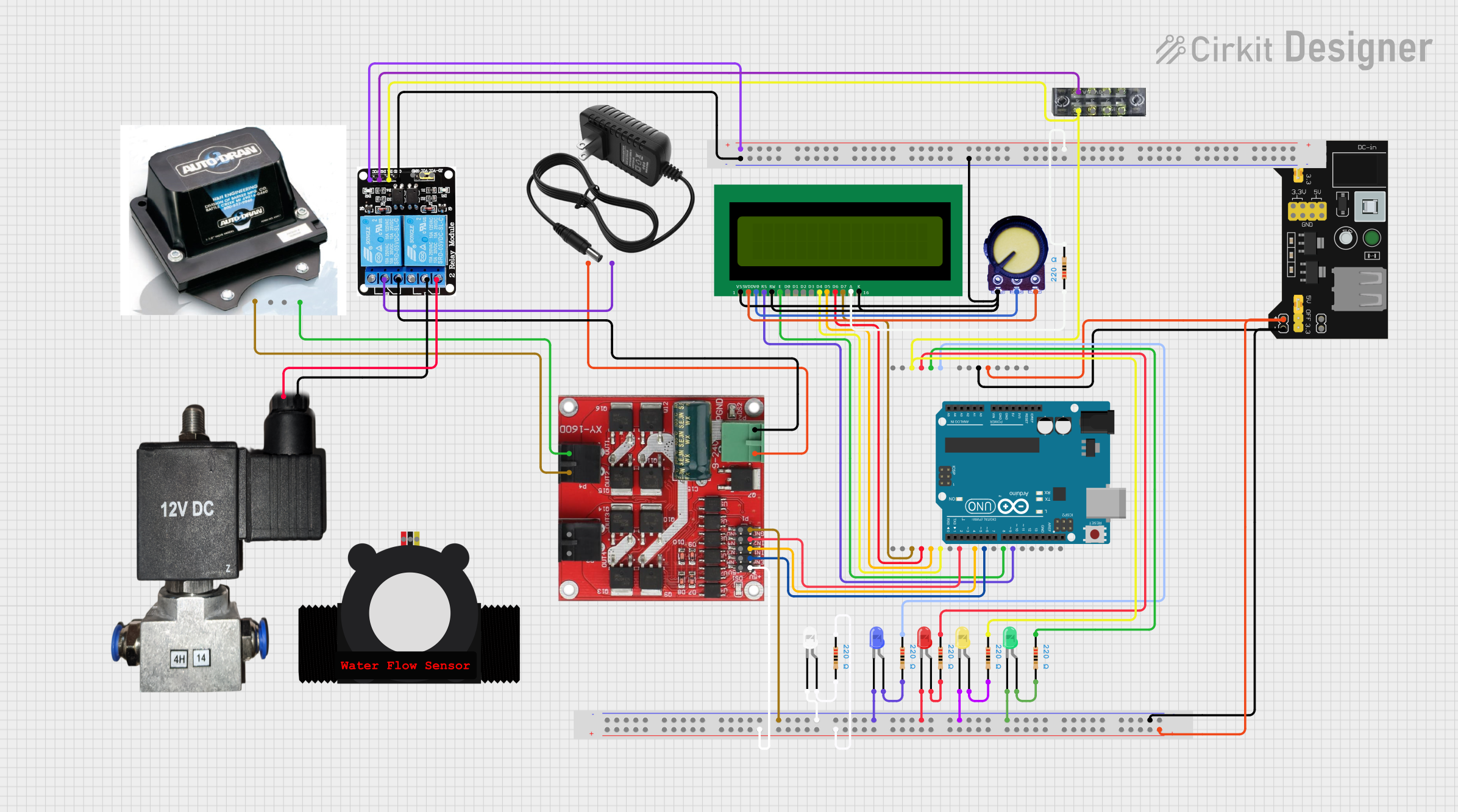
Circuit Documentation
Summary
This circuit is designed to automate the process of flushing and rinsing a tank using an Arduino UNO microcontroller. The system includes various components such as LEDs, a motor speed controller, a water flow meter, an LCD display, and a relay module. The Arduino UNO controls the operation of these components based on the programmed logic to ensure the tank is properly flushed and rinsed.
Component List
Arduino UNO
- Description: Microcontroller board based on the ATmega328P.
- Pins: UNUSED, IOREF, Reset, 3.3V, 5V, GND, Vin, A0, A1, A2, A3, A4, A5, SCL, SDA, AREF, D13, D12, D11, D10, D9, D8, D7, D6, D5, D4, D3, D2, D1, D0
L298 Dual H Bridge Motor Speed Controller
- Description: Motor driver module for controlling the speed and direction of DC motors.
- Pins: 5V, ENA, IN1, IN2, GND, IN4, IN3, 12V, Motor 1 Power, Motor 1 GND, Motor 2 Power, Motor 2 GND
LED: Two Pin (red)
- Description: Red LED for indicating status.
- Pins: cathode, anode
LED: Two Pin (yellow)
- Description: Yellow LED for indicating status.
- Pins: cathode, anode
Barker Auto Drain
- Description: Automatic drain valve for the tank.
- Pins: Brown Wire 12 V-, White Wire 12 V+, Yellow Wire (Switched), Green Wire (Switched)
YF-S201 Water Flow Meter
- Description: Water flow sensor for measuring the flow rate.
- Pins: SIG, GND, VCC
16X2 LCD
- Description: 16x2 character LCD display for showing status messages.
- Pins: VSS, VDD, V0, RS, RW, E, D1, D0, D2, D3, D4, D6, D5, D7, A, K
Potentiometer
- Description: Variable resistor for adjusting the contrast of the LCD.
- Pins: GND, Output, VCC
12v power supply
- Description: Power supply providing 12V DC.
- Pins: +, -
MB102 Breadboard Power Supply Module 3.3V/5V
- Description: Power supply module for breadboard providing 3.3V and 5V.
- Pins: VCC, GND, 3.3V, 5V
BreadBoard
- Description: Breadboard for prototyping and connecting components.
- Pins: Multiple pins for connections
5v 2-Relay JD-VCC
- Description: Relay module for switching high power devices.
- Pins: JD-VCC, VCC, GND, IN1, IN2, NO, COM, NC
LED: Two Pin (green)
- Description: Green LED for indicating status.
- Pins: cathode, anode
Resistor
- Description: Resistor for current limiting.
- Pins: pin1, pin2
- Properties: Resistance: 220 Ohms
LED: Two Pin (blue)
- Description: Blue LED for indicating status.
- Pins: cathode, anode
LED: Two Pin (white)
- Description: White LED for indicating status.
- Pins: cathode, anode
terminalblock-04-01
- Description: Terminal block for connecting wires.
- Pins: 1, 2, 3, 4, 5, 6, 7, 8
12v Pneumatic solenoid valve
- Description: Solenoid valve for controlling the flow of air or liquid.
- Pins: VCC, GND
Wiring Details
Arduino UNO
- 5V connected to MB102 Breadboard Power Supply Module 3.3V/5V VCC and BreadBoard pin3Z.
- GND connected to MB102 Breadboard Power Supply Module 3.3V/5V GND and BreadBoard pin4Y.
- A0 connected to Resistor pin1.
- A1 connected to Resistor pin1.
- A2 connected to Resistor pin1.
- A3 connected to Resistor pin1, terminalblock-04-01 pin7, and 5v 2-Relay JD-VCC IN1.
- D12 connected to 16X2 LCD RS.
- D11 connected to 16X2 LCD E.
- D9 connected to L298 Dual H Bridge Motor Speed Controller ENA.
- D8 connected to L298 Dual H Bridge Motor Speed Controller IN1.
- D7 connected to L298 Dual H Bridge Motor Speed Controller IN2.
- D5 connected to 16X2 LCD D4.
- D4 connected to 16X2 LCD D5.
- D3 connected to 16X2 LCD D6.
- D2 connected to 16X2 LCD D7.
L298 Dual H Bridge Motor Speed Controller
- ENA connected to Arduino UNO D9.
- IN1 connected to Arduino UNO D8.
- IN2 connected to Arduino UNO D7.
- 5V connected to BreadBoard pin45Z.
- GND connected to BreadBoard pin43Y.
- 12V connected to 12v power supply +.
- Motor 2 Power connected to Barker Auto Drain Brown Wire 12 V-.
- Motor 2 GND connected to Barker Auto Drain Green Wire (Switched).
LED: Two Pin (red)
- cathode connected to BreadBoard pin28Y.
- anode connected to Resistor pin2.
LED: Two Pin (yellow)
- cathode connected to BreadBoard pin24Y.
- anode connected to Resistor pin2.
Barker Auto Drain
- Brown Wire 12 V- connected to L298 Dual H Bridge Motor Speed Controller Motor 2 Power.
- Green Wire (Switched) connected to L298 Dual H Bridge Motor Speed Controller Motor 2 GND.
16X2 LCD
- RS connected to Arduino UNO D12.
- E connected to Arduino UNO D11.
- D4 connected to Arduino UNO D5.
- D5 connected to Arduino UNO D4.
- D6 connected to Arduino UNO D3.
- D7 connected to Arduino UNO D2.
- VSS connected to BreadBoard pin27Y.
- VDD connected to Potentiometer VCC.
- V0 connected to Potentiometer Output.
- K connected to BreadBoard pin27Y.
- RW connected to BreadBoard pin27Y.
- A connected to Resistor pin1.
Potentiometer
- GND connected to BreadBoard pin27Y.
- VCC connected to 16X2 LCD VDD.
- Output connected to 16X2 LCD V0.
12v power supply
- + connected to L298 Dual H Bridge Motor Speed Controller 12V.
- - connected to 5v 2-Relay JD-VCC COM.
MB102 Breadboard Power Supply Module 3.3V/5V
- VCC connected to BreadBoard pin3Z and Arduino UNO 5V.
- GND connected to BreadBoard pin4Y and Arduino UNO GND.
5v 2-Relay JD-VCC
- GND connected to BreadBoard pin3Y.
- IN1 connected to Resistor pin1, terminalblock-04-01 pin7, and Arduino UNO A3.
- IN2 connected to terminalblock-04-01 pin8.
- VCC connected to BreadBoard pin3Z.
- COM connected to 12v power supply - and 12v Pneumatic solenoid valve GND.
- NC connected to L298 Dual H Bridge Motor Speed Controller GND and 12v Pneumatic solenoid valve VCC.
LED: Two Pin (green)
- cathode connected to **Bread