
Arduino UNO-Based Temperature-Controlled Water Pump and Fan System with LCD Display
View and Edit Project In Cirkit Designer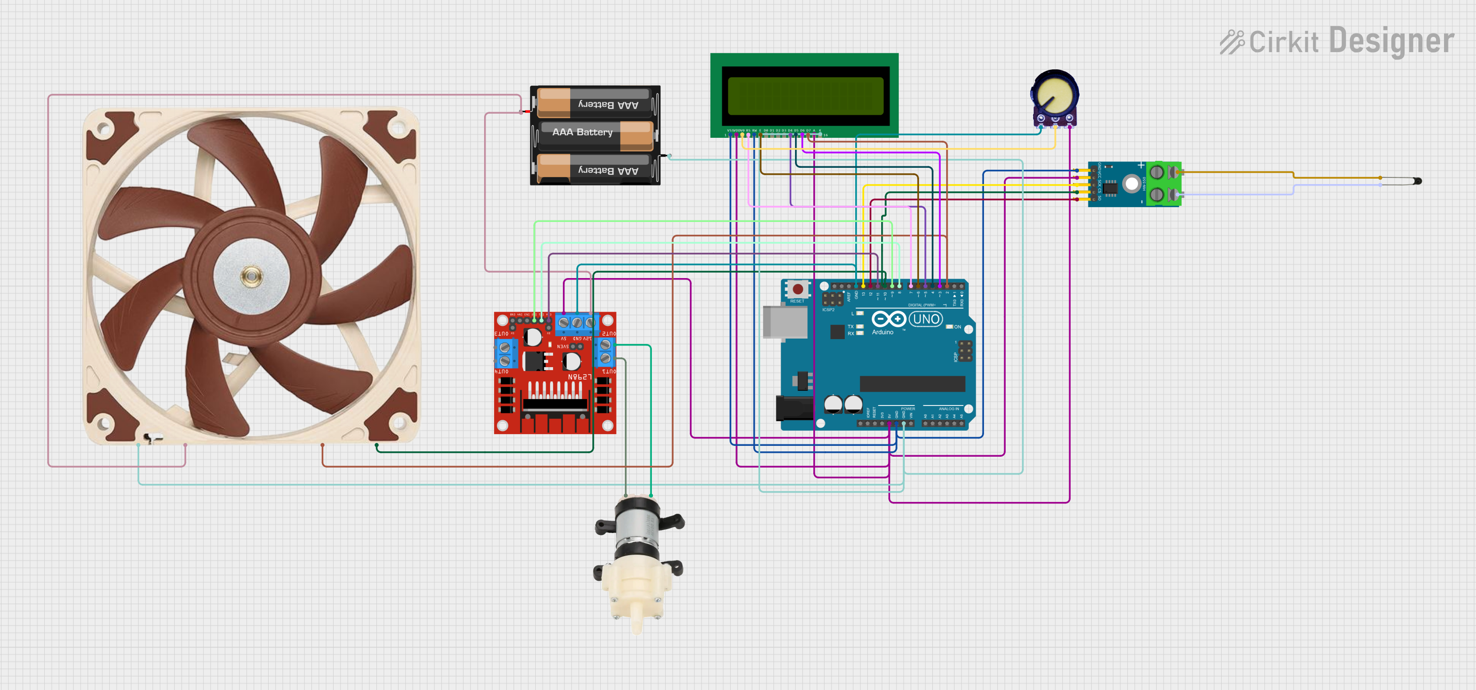
Circuit Documentation
Summary
This circuit is designed to control a 12V PWM fan and a mini diaphragm water pump based on temperature readings from a thermocouple. The temperature data is displayed on a 16x2 LCD screen. The circuit uses an Arduino UNO as the main microcontroller, interfacing with a MAX6675 thermocouple module, an L298N motor driver, a 12V PWM fan, a mini diaphragm water pump, a 3xAA battery pack, an NTC thermistor, a potentiometer, and a 16x2 LCD display.
Component List
Arduino UNO
- Description: Main microcontroller for the circuit.
- Pins: UNUSED, IOREF, Reset, 3.3V, 5V, GND, Vin, A0, A1, A2, A3, A4, A5, SCL, SDA, AREF, D13, D12, D11, D10, D9, D8, D7, D6, D5, D4, D3, D2, D1, D0
MAX6675 Module
- Description: Thermocouple interface module.
- Pins: GND, VCC, SCK, CS, SO, -, +
12V PWM Fan (120mm)
- Description: Cooling fan with PWM control.
- Pins: GND, +12V, TACH, PWM
Mini Diaphragm Water Pump
- Description: Water pump for liquid circulation.
- Pins: Positive (+), Negative (-)
3xAA Battery
- Description: Power supply for the circuit.
- Pins: VCC, GND
L298N DC Motor Driver
- Description: Motor driver for controlling the water pump.
- Pins: OUT1, OUT2, 12V, GND, 5V, OUT3, OUT4, 5V-ENA-JMP-I, 5V-ENA-JMP-O, +5V-J1, +5V-J2, ENA, IN1, IN2, IN3, IN4, ENB
NTC
- Description: Thermistor for temperature sensing.
- Pins: A0, A1
16x2 LCD
- Description: Display module for showing temperature and fan status.
- Pins: VSS, VDD, V0, RS, RW, E, D1, D0, D2, D3, D4, D6, D5, D7, A, K
Potentiometer
- Description: Variable resistor for adjusting LCD contrast.
- Pins: GND, Output, VCC
Wiring Details
Arduino UNO
- 5V: Connected to 5V pin of L298N DC motor driver, VDD and A pins of 16x2 LCD, VCC pin of MAX6675 Module, and VCC pin of Potentiometer.
- GND: Connected to GND pins of 16x2 LCD, MAX6675 Module, 12V PWM Fan, 3xAA Battery, and Potentiometer.
- D13: Connected to SCK pin of MAX6675 Module.
- D12: Connected to SO pin of MAX6675 Module.
- D11: Connected to ENA pin of L298N DC motor driver.
- D10: Connected to PWM pin of 12V PWM Fan and CS pin of MAX6675 Module.
- D9: Connected to IN2 pin of L298N DC motor driver.
- D8: Connected to IN1 pin of L298N DC motor driver.
- D7: Connected to RS pin of 16x2 LCD.
- D6: Connected to E pin of 16x2 LCD.
- D5: Connected to D4 pin of 16x2 LCD.
- D4: Connected to D5 pin of 16x2 LCD.
- D3: Connected to D6 pin of 16x2 LCD.
- D2: Connected to TACH pin of 12V PWM Fan and D7 pin of 16x2 LCD.
MAX6675 Module
- VCC: Connected to 5V pin of Arduino UNO.
- GND: Connected to GND pin of Arduino UNO.
- SCK: Connected to D13 pin of Arduino UNO.
- CS: Connected to D10 pin of Arduino UNO.
- SO: Connected to D12 pin of Arduino UNO.
- -: Connected to A1 pin of NTC.
- +: Connected to A0 pin of NTC.
12V PWM Fan (120mm)
- GND: Connected to GND pin of Arduino UNO.
- +12V: Connected to 12V pin of L298N DC motor driver.
- TACH: Connected to D2 pin of Arduino UNO.
- PWM: Connected to D10 pin of Arduino UNO.
Mini Diaphragm Water Pump
- Positive (+): Connected to OUT2 pin of L298N DC motor driver.
- Negative (-): Connected to OUT1 pin of L298N DC motor driver.
3xAA Battery
- VCC: Connected to 12V pin of L298N DC motor driver.
- GND: Connected to GND pin of Arduino UNO.
L298N DC Motor Driver
- 5V: Connected to 5V pin of Arduino UNO.
- GND: Connected to GND pin of Arduino UNO.
- ENA: Connected to D11 pin of Arduino UNO.
- IN1: Connected to D8 pin of Arduino UNO.
- IN2: Connected to D9 pin of Arduino UNO.
- 12V: Connected to +12V pin of 12V PWM Fan and VCC pin of 3xAA Battery.
- OUT1: Connected to Negative (-) pin of Mini Diaphragm Water Pump.
- OUT2: Connected to Positive (+) pin of Mini Diaphragm Water Pump.
NTC
- A0: Connected to + pin of MAX6675 Module.
- A1: Connected to - pin of MAX6675 Module.
16x2 LCD
- VDD: Connected to 5V pin of Arduino UNO.
- VSS: Connected to GND pin of Arduino UNO.
- V0: Connected to Output pin of Potentiometer.
- RS: Connected to D7 pin of Arduino UNO.
- RW: Connected to GND pin of Arduino UNO.
- E: Connected to D6 pin of Arduino UNO.
- D4: Connected to D5 pin of Arduino UNO.
- D5: Connected to D4 pin of Arduino UNO.
- D6: Connected to D3 pin of Arduino UNO.
- D7: Connected to D2 pin of Arduino UNO.
- A: Connected to 5V pin of Arduino UNO.
- K: Connected to GND pin of Arduino UNO.
Potentiometer
- GND: Connected to GND pin of Arduino UNO.
- Output: Connected to V0 pin of 16x2 LCD.
- VCC: Connected to 5V pin of Arduino UNO.
Code Documentation
sketch.ino
void setup() {
  // put your setup code here, to run once:

}

void loop() {
  // put your main code here, to run repeatedly:

}
documentation.txt
#include <Adafruit_MAX31855.h>
#include <LiquidCrystal.h>

// Thermocouple Pins
#define thermoDO 12
#define thermoCS 10
#define thermoCLK 13
Adafruit_MAX31855 thermocouple(thermoCLK, thermoCS, thermoDO);

// L298N Pump Control Pins
#define PUMP_IN1 8
#define PUMP_IN2 9
#define PUMP_ENA 11

// 4-Wire Fan Control Pins
#define FAN_PWM 10
#define FAN_TACH 2

// LCD Configuration
LiquidCrystal lcd(7, 6, 5, 4, 3, 2); // RS, E, D4, D5, D6, D7

// Fan RPM Variables
volatile int tachCounter = 0;
unsigned long lastRPMCheck = 0;
int rpm = 0;

// Temperature Variables
float temperature = 0.0;

// Tachometer Interrupt Function
void countTach() {
  tachCounter++;
}

void setup() {
  // Serial Communication
  Serial.begin(9600);

  // LCD Initialization
  lcd.begin(16, 2);
  lcd.print("System Initializing");
  delay(2000);
  lcd.clear();

  // Pump Control Pins
  pinMode(PUMP_IN1, OUTPUT);
  pinMode(PUMP_IN2, OUTPUT);
  pinMode(PUMP_ENA, OUTPUT);

  // Fan Control Pins
  pinMode(FAN_PWM, OUTPUT);
  pinMode(FAN_TACH, INPUT_PULLUP);
  attachInterrupt(digitalPinToInterrupt(FAN_TACH), countTach, FALLING);

  // Initial State: Turn off pump and fan
  digitalWrite(PUMP_IN1, LOW);
  digital