Cirkit Designer
Your all-in-one circuit design IDE
Home /
Project Documentation
Arduino Mega 2560-Based Autonomous Robot with IR and Ultrasonic Sensors
Circuit Documentation
Summary
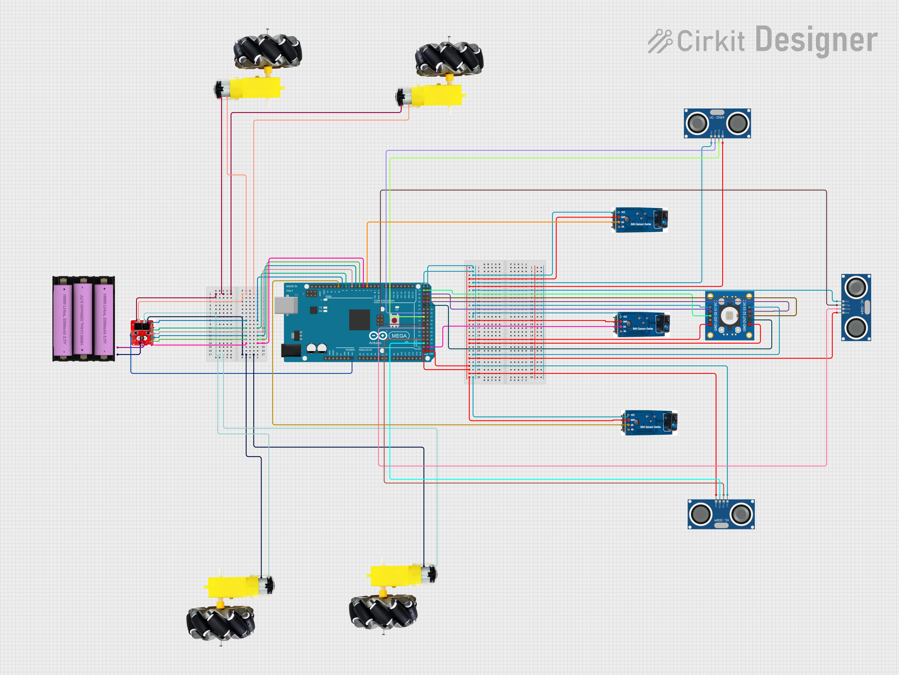
This document provides a detailed overview of a circuit that includes an Arduino Mega 2560 microcontroller, multiple TCRT-5000 IR sensors, HC-SR04 Ultrasonic Sensors, a TCS3200 color sensor, motor and wheels, a motor driver, and a 7V battery. The circuit is designed to interface various sensors and actuators with the Arduino Mega 2560 for a range of functionalities.
Component List
Arduino Mega 2560
- Description: A microcontroller board based on the ATmega2560.
- Pins: IOREF, RESET, 3V3, 5V, GND, VIN, A0-A15, D0-D53, AREF, SDA, SCL
TCRT-5000 IR Sensor
- Description: An infrared sensor used for proximity detection.
- Pins: 5V, GND, D0, A0
HC-SR04 Ultrasonic Sensor
- Description: An ultrasonic sensor used for distance measurement.
- Pins: VCC, TRIG, ECHO, GND
TCS3200 Color Sensor
- Description: A color sensor that can detect and measure the color of an object.
- Pins: GND, OUT, S2, S3, VCC, LED, S0, S1
Motor and Wheels
- Description: A set of motors and wheels for movement.
- Pins: vcc, GND
Motor Driver
- Description: A motor driver used to control the motors.
- Pins: A1, B1, A2, B2, 7, 6, 8, 9, 4, 5, VIN, P+, P-
Set Battery (7V)
- Description: A 7V battery used to power the circuit.
- Pins: +, -
Wiring Details
Arduino Mega 2560
- VIN: Connected to VIN of Motor Driver
- D3 PWM: Connected to D0 of TCRT-5000 IR Sensor
- D4 PWM: Connected to pin 4 of Motor Driver
- D5 PWM: Connected to pin 5 of Motor Driver
- D6 PWM: Connected to pin 6 of Motor Driver
- D7 PWM: Connected to pin 7 of Motor Driver
- D8 PWM: Connected to pin 8 of Motor Driver
- D9 PWM: Connected to pin 9 of Motor Driver
- D10 PWM: Connected to D0 of TCRT-5000 IR Sensor
- GND: Connected to GND of all sensors and components
- D50: Connected to ECHO of HC-SR04 Ultrasonic Sensor
- D48: Connected to TRIG of HC-SR04 Ultrasonic Sensor
- D42: Connected to ECHO of HC-SR04 Ultrasonic Sensor
- D40: Connected to TRIG of HC-SR04 Ultrasonic Sensor
- D36: Connected to ECHO of HC-SR04 Ultrasonic Sensor
- D34: Connected to TRIG of HC-SR04 Ultrasonic Sensor
- D30: Connected to OUT of TCS3200 Color Sensor
- D28: Connected to S3 of TCS3200 Color Sensor
- D26: Connected to S2 of TCS3200 Color Sensor
- D24: Connected to S1 of TCS3200 Color Sensor
- D22: Connected to S0 of TCS3200 Color Sensor
- 5V: Connected to 5V of all sensors and components
TCRT-5000 IR Sensor
- D0: Connected to D3 PWM of Arduino Mega 2560
- D0: Connected to D10 PWM of Arduino Mega 2560
- D0: Connected to D53 of Arduino Mega 2560
- GND: Connected to GND of Arduino Mega 2560
- 5V: Connected to 5V of Arduino Mega 2560
HC-SR04 Ultrasonic Sensor
- ECHO: Connected to D50 of Arduino Mega 2560
- TRIG: Connected to D48 of Arduino Mega 2560
- ECHO: Connected to D42 of Arduino Mega 2560
- TRIG: Connected to D40 of Arduino Mega 2560
- ECHO: Connected to D36 of Arduino Mega 2560
- TRIG: Connected to D34 of Arduino Mega 2560
- GND: Connected to GND of Arduino Mega 2560
- VCC: Connected to 5V of Arduino Mega 2560
TCS3200 Color Sensor
- OUT: Connected to D30 of Arduino Mega 2560
- S3: Connected to D28 of Arduino Mega 2560
- S2: Connected to D26 of Arduino Mega 2560
- S1: Connected to D24 of Arduino Mega 2560
- S0: Connected to D22 of Arduino Mega 2560
- GND: Connected to GND of Arduino Mega 2560
- VCC: Connected to 5V of Arduino Mega 2560
Motor and Wheels
- vcc: Connected to A1 of Motor Driver
- vcc: Connected to A2 of Motor Driver
- GND: Connected to B1 of Motor Driver
- GND: Connected to B2 of Motor Driver
Motor Driver
- VIN: Connected to VIN of Arduino Mega 2560
- 4: Connected to D4 PWM of Arduino Mega 2560
- 5: Connected to D5 PWM of Arduino Mega 2560
- 6: Connected to D6 PWM of Arduino Mega 2560
- 7: Connected to D7 PWM of Arduino Mega 2560
- 8: Connected to D8 PWM of Arduino Mega 2560
- 9: Connected to D9 PWM of Arduino Mega 2560
- A1: Connected to vcc of Motor and Wheels
- B1: Connected to GND of Motor and Wheels
- A2: Connected to vcc of Motor and Wheels
- B2: Connected to GND of Motor and Wheels
- P+: Connected to + of Set Battery (7V)
- P-: Connected to - of Set Battery (7V)
Set Battery (7V)
- +: Connected to P+ of Motor Driver
- -: Connected to P- of Motor Driver
Documented Code
Arduino Mega 2560 Code (sketch.ino)
void setup() {
  // put your setup code here, to run once:

}

void loop() {
  // put your main code here, to run repeatedly:

}
Documentation (documentation.txt)
This document provides a comprehensive overview of the circuit, including a summary, component list, wiring details, and documented code. Each component is described, and its connections are detailed to ensure clarity and ease of understanding.