Cirkit Designer
Your all-in-one circuit design IDE
Home /
Project Documentation
Arduino Mega 2560 Controlled Environment System with Relay, Humidifier, Fan, and Indicator LEDs
Circuit Documentation
Summary
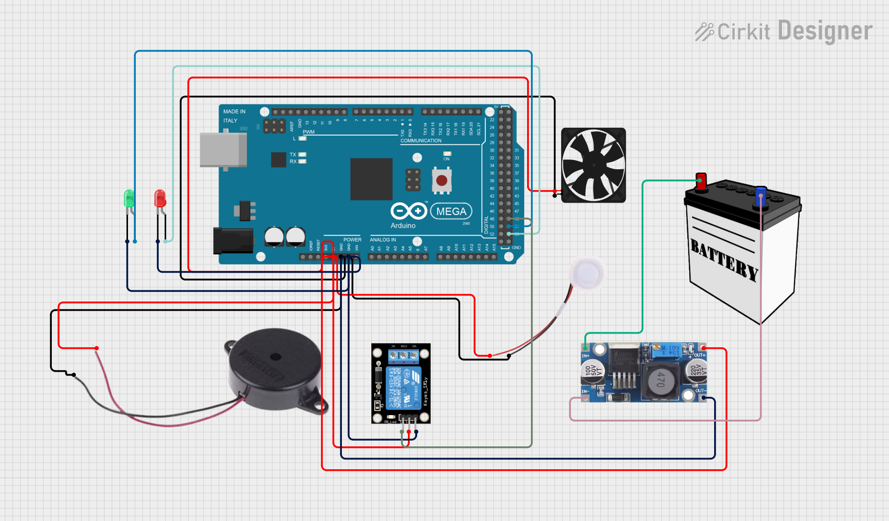
This circuit is designed to control a humidifier, a fan, and a buzzer, with the capability to indicate status through red and green LEDs. The system is powered by a 12V battery, with a step-down buck converter to provide the necessary 5V supply. An Arduino Mega 2560 serves as the central microcontroller unit, interfacing with a KY-019 relay module to control the power flow to the humidifier. The circuit's design allows for expansion and integration with additional sensors or actuators if needed.
Component List
Arduino Mega 2560
- Microcontroller board based on the ATmega2560
- Provides a large number of IO pins for interfacing with various components
Humidifier
- A device that increases humidity (moisture) in a single room or an entire building
Buzzer
- An audio signaling device, which may be mechanical, electromechanical, or piezoelectric
Fan
- An electric device that blows air
LED: Two Pin (red)
- A red light-emitting diode that can be used as an indicator
LED: Two Pin (green)
- A green light-emitting diode that can be used as an indicator
KY-019 Relay module 1 channel
- A relay module that can be used to control high power/high voltage devices
Step down Buck converter
- A DC-DC power converter that steps down voltage from its input to its output
12V Battery
- A battery providing a 12V supply to power the circuit
Wiring Details
Arduino Mega 2560
- 5V: Connected to the 5V supply net
- GND: Connected to the ground net
- D53: Connected to the anode of the red LED
- D51: Connected to the anode of the green LED
- D49: Connected to the signal pin of the KY-019 relay module
Humidifier
- 5V: Connected to the 5V supply net
- GND: Connected to the ground net
Buzzer
- POSITIVE: Connected to the 5V supply net
- NEGATIVE: Connected to the ground net
Fan
- 5V: Connected to the 5V supply net
- GND: Connected to the ground net
LED: Two Pin (red)
- Anode: Connected to pin D53 on the Arduino Mega 2560
- Cathode: Connected to the ground net
LED: Two Pin (green)
- Anode: Connected to pin D51 on the Arduino Mega 2560
- Cathode: Connected to the ground net
KY-019 Relay module 1 channel
- 5V: Connected to the 5V supply net
- GND: Connected to the ground net
- S: Connected to pin D49 on the Arduino Mega 2560
Step down Buck converter
- IN +: Connected to the VCC of the 12V battery
- IN - GND: Connected to the GND of the 12V battery
- OUT +: Connected to the 5V supply net
- OUT - GND: Connected to the ground net
12V Battery
- VCC: Connected to the IN + of the step-down buck converter
- GND: Connected to the IN - GND of the step-down buck converter
Documented Code
Arduino Mega 2560 - sketch.ino
void setup() {
  // put your setup code here, to run once:

}

void loop() {
  // put your main code here, to run repeatedly:

}
Arduino Mega 2560 - documentation.txt
(No additional documentation provided for the code)