
Arduino Nano Controlled Servo and LED System with NRF24L01 Wireless Communication
View and Edit Project In Cirkit Designer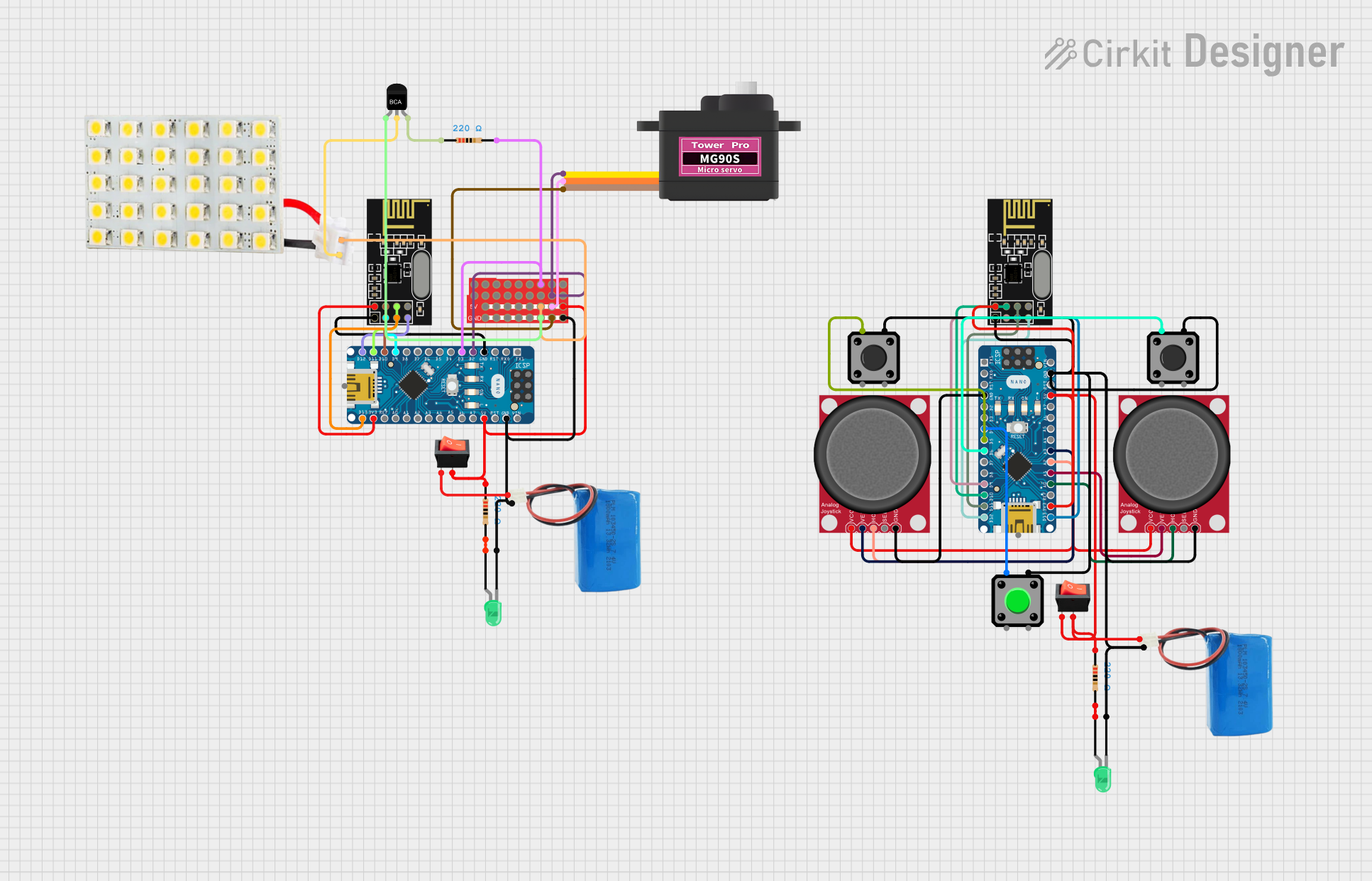
Circuit Documentation
Summary
This circuit is designed to receive signals from a transmitter to control LEDs and a servo motor. It includes two Arduino Nano microcontrollers, NRF24L01 wireless modules for communication, a servomotor, analog joysticks, tactile switch buttons, a pushbutton, LEDs, resistors, a transistor, batteries, and rocker switches. The primary Arduino Nano is configured to control a servomotor and toggle the state of an LED based on the received RF signals. It also allows for manual adjustment of the servo position using two tactile switch buttons. The secondary Arduino Nano's code is not provided, suggesting it may be used for future expansion or currently serves a simple or placeholder function.
Component List
Microcontrollers
- Arduino Nano: A compact microcontroller board based on the ATmega328P, featuring digital and analog I/O pins.
Communication Modules
- NRF24L01: A 2.4GHz wireless transceiver module used for RF communication.
Input Devices
- Analog Joystick (Wokwi Compatible): A joystick module with vertical and horizontal analog outputs and a select button.
- Tactile Switch Buttons - 12mm Square: Simple push-to-make buttons for user input.
- Pushbutton: A standard pushbutton used for triggering actions.
Output Devices
- Servomotor MG90S: A small and lightweight servomotor for precise angular movement.
- LED Board: A board with an LED for visual output.
- LED: Two Pin (green): Green LEDs used for status indication.
Power Supply
- 5v battery: A power source providing a 5V supply to the circuit.
- Rocker switch: A switch used to control the power supply to parts of the circuit.
Passive Components
- Resistor: A component used to limit current or divide voltages in the circuit.
- NPN-Transistor: A transistor used as a switch or amplifier.
Prototyping Boards
- ProtoSnap - Pro Mini - Protoboard: A prototyping board used for making temporary circuit connections.
Wiring Details
Arduino Nano
- GND: Connected to the ground of NRF24L01, battery, green LED, and other GND connections.
- D2: Connected to the servo signal pin and ProtoSnap board.
- D3: Connected to a resistor leading to the base of an NPN transistor.
- D9: Connected to the CE pin of NRF24L01.
- D10: Connected to the CSN pin of NRF24L01.
- D11/MOSI: Connected to the MOSI pin of NRF24L01.
- D12/MISO: Connected to the MISO pin of NRF24L01.
- 5V: Connected to the ProtoSnap board, a resistor, and the VCC of the analog joystick.
- 3V3: Connected to the VCC (3V) of NRF24L01.
- D13/SCK: Connected to the SCK pin of NRF24L01.
- A0-A3: Connected to the horizontal and vertical pins of the analog joysticks.
NRF24L01
- GND: Connected to the ground of Arduino Nano.
- MOSI: Connected to the MOSI pin of Arduino Nano.
- CSN: Connected to the D10 pin of Arduino Nano.
- VCC (3V): Connected to the 3V3 pin of Arduino Nano.
- CE: Connected to the D9 pin of Arduino Nano.
- SCK: Connected to the D13/SCK pin of Arduino Nano.
- MISO: Connected to the D12/MISO pin of Arduino Nano.
Servomotor MG90S
- SIG: Connected to the D2 pin of Arduino Nano.
- VCC: Connected to the ProtoSnap board.
- GND: Connected to the ProtoSnap board.
Analog Joystick (Wokwi Compatible)
- VCC: Connected to the 5V pin of Arduino Nano through a rocker switch.
- VERT: Connected to the A3 pin of Arduino Nano.
- HORZ: Connected to the A2 pin of Arduino Nano.
- GND: Connected to the ground of Arduino Nano.
Tactile Switch Buttons - 12mm Square
- 1: Connected to the D5 and D6 pins of Arduino Nano for one button, and to the green LED for the other button.
- 2: Connected to the ground of Arduino Nano and the cathode of the green LED.
Pushbutton
- Pin 1: Connected to the D4 pin of Arduino Nano.
- Pin 4: Connected to the ground of Arduino Nano.
LED: Two Pin (green)
- Cathode: Connected to the ground through a resistor.
- Anode: Connected to the 5V pin of Arduino Nano through a resistor.
Resistor
- Pin 1: Connected to the 5V pin of Arduino Nano and the anode of the green LED.
- Pin 2: Connected to the cathode of the green LED and the base of the NPN transistor.
NPN-Transistor
- E: Connected to the ProtoSnap board.
- C: Connected to the GND of the LED Board.
- B: Connected to the D3 pin of Arduino Nano through a resistor.
ProtoSnap - Pro Mini - Protoboard
- Used for making connections between various components such as the servomotor, NPN transistor, and LED Board.
5v battery
- Positive: Connected to the rocker switch and the ProtoSnap board.
- Negative: Connected to the ground of Arduino Nano and other components.
Rocker switch
- Used to control the connection between the battery and the 5V supply line of the circuit.
Documented Code
Receiver Code for Arduino Nano (Instance ID: 08f9f7ca-670a-4772-8cdc-e666b82695dd)
/*
 * Receiver Code
 * This code receives signals from the transmitter to control LEDs and a servo.
 * The green button toggles LEDs, the right joystick controls the servo, and
 * two black buttons fine-tune the servo position.
 */

#include <SPI.h>
#include <nRF24L01.h>
#include <RF24.h>
#include <Servo.h>

#define LED_PIN 7
#define SERVO_PIN 2
#define BUTTON_LEFT_PIN 5
#define BUTTON_RIGHT_PIN 6

RF24 radio(9, 10); // CE, CSN
const byte address[6] = "00001";
Servo myServo;

int ledState = LOW;
int servoPos = 90;

void setup() {
  pinMode(LED_PIN, OUTPUT);
  pinMode(BUTTON_LEFT_PIN, INPUT_PULLUP);
  pinMode(BUTTON_RIGHT_PIN, INPUT_PULLUP);
  myServo.attach(SERVO_PIN);
  myServo.write(servoPos);
  radio.begin();
  radio.openReadingPipe(0, address);
  radio.setPALevel(RF24_PA_MIN);
  radio.startListening();
}

void loop() {
  if (radio.available()) {
    char text[32] = "";
    radio.read(&text, sizeof(text));
    if (strcmp(text, "TOGGLE_LED") == 0) {
      ledState = !ledState;
      digitalWrite(LED_PIN, ledState);
    } else if (strncmp(text, "SERVO", 5) == 0) {
      int pos = atoi(&text[5]);
      servoPos = constrain(pos, 0, 180);
      myServo.write(servoPos);
    }
  }
  if (digitalRead(BUTTON_LEFT_PIN) == LOW) {
    servoPos = max(servoPos - 1, 0);
    myServo.write(servoPos);
    delay(100);
  }
  if (digitalRead(BUTTON_RIGHT_PIN) == LOW) {
    servoPos = min(servoPos + 1, 180);
    myServo.write(servoPos);
    delay(100);
  }
}
Placeholder Code for Arduino Nano (Instance ID: bc002bc0-4900-43b4-975e-eefde7c74370)
void setup() {
  // put your setup code here, to run once:

}

void loop() {
  // put your main code here, to run repeatedly:

}
The second Arduino Nano does not have any specific functionality defined in the provided code. It may be used for future expansion or currently serves a simple or placeholder function.