
ESP32-Based Smart Weighing and Distance Measurement System with LED Indicators
View and Edit Project In Cirkit Designer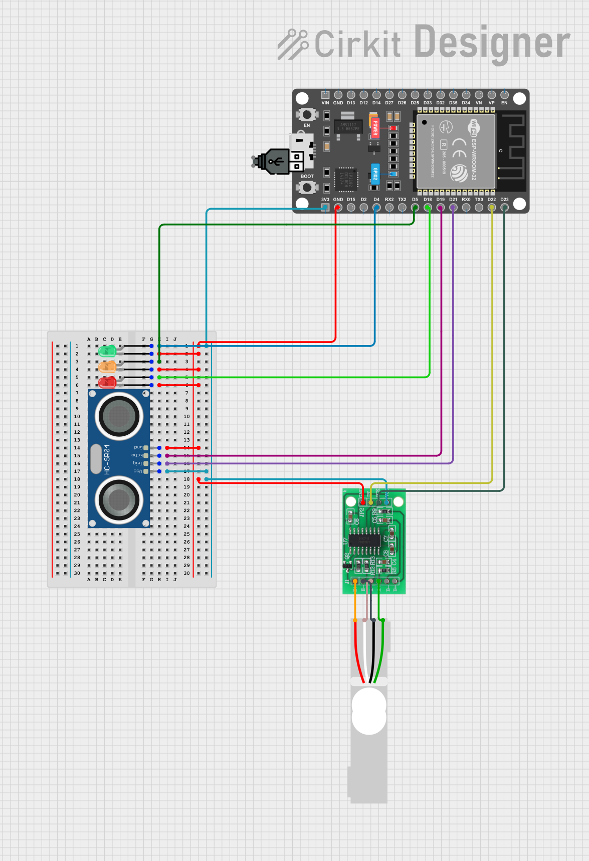
Circuit Documentation
Summary
This document provides a detailed overview of a circuit that includes a load cell, an HX711 bridge sensor interface, an HC-SR04 ultrasonic sensor, three LEDs (green, red, and orange), and an ESP32 DevKit V1 microcontroller. The circuit is designed to interface with various sensors and indicators, with the ESP32 serving as the central control unit.
Component List
Load Cell - Red/white/black/green
- Description: A load cell used for measuring weight or force.
- Pins: E+, A-, E-, A+
HX711 - Bridge Sensor Interface
- Description: An interface for bridge sensors, commonly used with load cells.
- Pins: E+, E-, A-, A+, B-, B+, GND - GROUND, DATA (OUT), SCK - CLOCK (IN), 3.3/3.5V Supply
HC-SR04 Ultrasonic Sensor
- Description: An ultrasonic sensor used for distance measurement.
- Pins: VCC, TRIG, ECHO, GND
LED: Two Pin (green)
- Description: A green LED used as an indicator.
- Pins: cathode, anode
LED: Two Pin (red)
- Description: A red LED used as an indicator.
- Pins: cathode, anode
LED: Two Pin (orange)
- Description: An orange LED used as an indicator.
- Pins: cathode, anode
ESP 32 DEVKIT V1 (30 pins)
- Description: A development board based on the ESP32 microcontroller.
- Pins: EN, VP, VN, D34, D35, D32, D33, D25, D26, D27, D14, D12, D13, GND, VIN, 3V3, D15, D2, D4, RX2, TX2, D5, D18, D19, D21, RX0, TX0, D22, D23
USB power
- Description: A USB power supply.
- Pins: +, -
Wiring Details
Load Cell - Red/white/black/green
- E+ connected to E+ of HX711
- A- connected to A- of HX711
- E- connected to E- of HX711
- A+ connected to A+ of HX711
HX711 - Bridge Sensor Interface
- E+ connected to E+ of Load Cell
- A- connected to A- of Load Cell
- E- connected to E- of Load Cell
- A+ connected to A+ of Load Cell
- GND - GROUND connected to GND of ESP32, GND of HC-SR04, cathode of green LED, cathode of red LED, cathode of orange LED
- DATA (OUT) connected to D22 of ESP32
- SCK - CLOCK (IN) connected to D23 of ESP32
- 3.3/3.5V Supply connected to 3V3 of ESP32, VCC of HC-SR04
HC-SR04 Ultrasonic Sensor
- VCC connected to 3.3/3.5V Supply of HX711, 3V3 of ESP32
- TRIG connected to D21 of ESP32
- ECHO connected to D19 of ESP32
- GND connected to GND of ESP32, GND - GROUND of HX711, cathode of green LED, cathode of red LED, cathode of orange LED
LED: Two Pin (green)
- anode connected to D4 of ESP32
- cathode connected to GND of ESP32, GND - GROUND of HX711, GND of HC-SR04, cathode of red LED, cathode of orange LED
LED: Two Pin (red)
- anode connected to D18 of ESP32
- cathode connected to GND of ESP32, GND - GROUND of HX711, GND of HC-SR04, cathode of green LED, cathode of orange LED
LED: Two Pin (orange)
- anode connected to D5 of ESP32
- cathode connected to GND of ESP32, GND - GROUND of HX711, GND of HC-SR04, cathode of green LED, cathode of red LED
ESP 32 DEVKIT V1 (30 pins)
- D4 connected to anode of green LED
- D5 connected to anode of orange LED
- D18 connected to anode of red LED
- D19 connected to ECHO of HC-SR04
- D21 connected to TRIG of HC-SR04
- D22 connected to DATA (OUT) of HX711
- D23 connected to SCK - CLOCK (IN) of HX711
- 3V3 connected to 3.3/3.5V Supply of HX711, VCC of HC-SR04
- GND connected to GND - GROUND of HX711, GND of HC-SR04, cathode of green LED, cathode of red LED, cathode of orange LED
Code
No code provided.